Take a quiz on the enclosed stage checklist
Try the flashcards first then test your retained knowledge with the quiz.
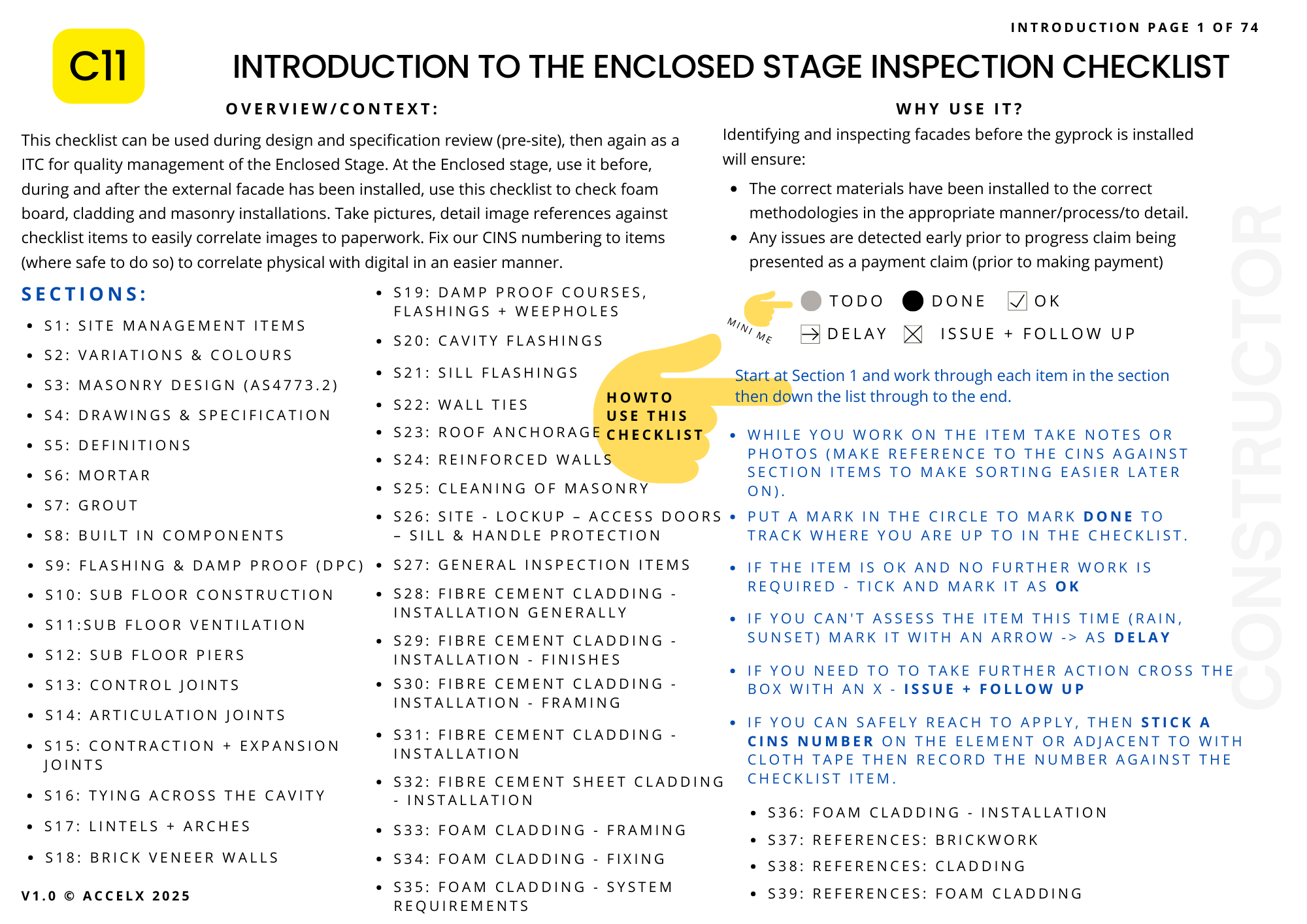
Quality Management Checklist Access
All our published checklists are available to download via the Checklists Link in the navigation menu or directly at https://www.constructor.net.au/checklists/. Please note: You’ll need to be a member and to log in to access the content.

Update
This checklist took over 6 weeks to draft then to publish - its our beefiest yet.
Introduction: What is the Enclosed Stage, and Why Should You Care?
When you're building a new home, one of the most exciting moments is seeing the walls go up and the outside start to take shape. This is known as the Enclosed Stage — when the external cladding (like bricks or cladding boards) has been installed, windows and doors are in, and your house is sealed from the weather. You might even start imagining where the couch will go. Its starting to shape and the spaces are making sense to you finally.
But this is also a critical point in the construction process. Why? Because what you can’t see behind the walls matters just as much as what you can. If things like wall ties, damp-proofing, and ventilation haven’t been done properly, it can lead to serious problems down the track — like mould, water leaks, or cracking brickwork.
That’s where our C11 Enclosed Stage Inspection Checklist comes in.
This checklist helps you — the homeowner — inspect your house during this phase to make sure everything is on track and up to standard. It's based on Australian Standards and covers things like brickwork, cladding systems, flashing, ventilation, and how well your builder is managing the site overall.
And no, you don’t have to be a building expert to use it. This guide will walk you through the checklist step by step, explaining what to look for in plain English. We’ll help you spot potential red flags before they turn into expensive fixes — and give you the confidence to have meaningful conversations with your builder.
Section 1: Site Management – What's Happening Around Your Build?
Before we even look at the walls, let's start with what’s happening on the ground — literally. A messy site isn’t just an eyesore, it can also cause damage to neighbouring properties, create safety hazards, and even lead to fines for sediment runoff.
This first section of the C11 checklist focuses on site safety, cleanliness, and proper setup. It's all about making sure your builder is looking after the basics — which are surprisingly often overlooked.
On the other hand, a messy site shows lack of control, poor process and a "who care's" general attitude. The best phrase to square people up in construction is "would you do that on your new home" - if the answer is no - do it again so you'd be happy to have it.
S1: Site Management Items
This section is all about first impressions — but not just how the site looks. We're checking how well it's managed, how clean and safe it is, and whether it sets the stage for quality construction. Poor site management often leads to costly rework later.
What to Check
✅ Temporary Fencing
- Fencing must be secure, stable, and properly erected — no leaning panels or gaps.
- Should meet local council requirements (often 1.8m high) and fully enclose the site.
- Look for signage: safety, builder contact details, and site entry conditions must be displayed.
✅ Sediment and Erosion Control
- Ensure sediment barriers (like silt fencing or straw bales) are in place and intact.
- These help prevent soil runoff into drains — a legal and environmental requirement under most council guidelines.
- Check around the lowest points of the site and near footpaths or stormwater grates.
✅ Kerb and Gutter Protection
- Kerbs should be protected from damage and free of concrete slurry or debris.
- Temporary kerb ramps or protection mats should be used where heavy vehicle access is required.
✅ Site Cleanliness and Safety
- Rubbish should be contained (skip bins or mesh cages) and not spread across the site.
- Loose offcuts, nails, and broken bricks are a trip hazard — they should be removed.
- Clear pathways should be maintained around the perimeter of the house.
✅ Access for Trades and Vehicles
- There must be a designated vehicle access point (gravel, crushed rock, or stabilised track).
- Avoids muddy driveways and prevents sediment from being dragged onto public roads.
- Check for crossover protection if the site uses a council kerb or concrete driveway.
✅ Drainage Conditions
- Is water pooling around the slab or under the subfloor?
- Temporary downpipes or flexible hose must be connected to roof drainage to divert water away from the house.
✅ Underground Services Marking
- Sewer, stormwater, and water connections should be clearly marked.
- Electrical pits and NBN lead-ins should be protected from damage during heavy machinery access.
Why This Matters
Poor site management doesn't just look bad — it directly affects build quality.
- Unsafe or dirty sites = delays and injuries.
- Uncontrolled runoff = fines and slab issues.
- Blocked drainage = future movement and moisture problems.
It's often a strong indicator of how seriously the builder takes quality. If the basics aren't right, what else is being skipped?
Section 2: Variations & Colour Selections – Is What’s on Paper What’s Getting Built?
This part of the checklist makes sure that what you agreed to in your contract — especially in terms of looks and finishes — is actually what’s turning up on site.
This section is all about matching what’s built to what you actually signed off on. It’s surprisingly common for the wrong cladding, paint, brick, or roof tile to be delivered or installed — and the earlier you spot it, the easier it is to fix.
What to Check
✅ Façade, Colour & Finish Variations
- Double-check the actual materials onsite match your signed-off colour selections, samples, or variation documents.
- This includes bricks, mortar colour, roof tiles, fascia and gutter colour, render, cladding, and paint.
- Any differences between the contract, drawings, or colour schedule and what's onsite must be raised immediately — ideally before installation begins.
✅ Approved Variations Are Documented
- Any changes to colours, finishes, or material brands (e.g. switching from Colorbond to zincalume) must be formalised in a written variation, signed by both parties.
- Make sure the price difference (if any) is clearly documented.
- Verbal changes are not enforceable — if it’s not in writing, it didn’t happen.
✅ Material Deliveries Match What Was Specified
- Confirm delivery dockets for bricks, render base coats, tiles, and cladding.
- Cross-check the brand, range, and colour against your selections. For example:
- Brick = Austral Homestead in "Blackwood"
- Roof tile = Monier Elabana in "Barramundi"
- A small label or batch tag is not enough — open a few packs and check for consistent colour and finish.
✅ Finishes Installed in Correct Areas
- Some homes have multiple finishes (e.g. brick and cladding, or mixed colours). These must be placed in the correct zones as per the elevations and selections.
- Render or paint must be consistent and neatly applied. Edges should be clean and not oversprayed or uneven.
- Brick blends should be mixed from at least 3 packs to avoid colour banding or blotchy walls.
Why This Matters
- Mistakes with colours or finishes can ruin your façade — and be expensive to fix after the fact.
- The Builder may try to charge for rework, even if it’s their error — especially if you didn’t pick it up before installation.
- Worse, you may get stuck with something you don’t like and didn’t choose.
When you look at your brickwork - this is the song you want playing in your head.
🧱 Section 3: Masonry Design (AS4773.2 + AS3700) – Bricks That Stay Put and Walls That Don’t Crack
Understanding how your brickwork is meant to perform — not just look good
This section focuses on how your masonry (brick or block walls) should be designed and built to meet performance requirements — particularly around strength, durability, cracking, and long-term movement. The standard that applies here is AS 4773.2 – Masonry in small buildings, which sets the rules for design and construction.
Key Areas to Check
✅ Serviceability and Support Requirements
- Masonry must be properly supported — including over openings, at floor level, and around openings like windows and doors.
- Look for signs of overhanging bricks or unsupported loads. Every part of the brick wall should have continuous support underneath.
- Where walls bear on concrete slabs or lintels, full bearing is required (no gaps, overhangs, or misalignment).
✅ Durability and Exposure Classifications
- Masonry must suit its exposure zone — for example, areas near the coast (Zone C or D) require higher durability materials and mixes.
- Mortar and grout must also match the durability class — this includes selecting the right cement and sand blends.
- Check for material compatibility (e.g. galvanised ties or stainless steel in aggressive environments).
✅ Movement Control & Cracking Prevention
- Movement joints (like control joints and articulation joints) must be included and correctly spaced to prevent cracking due to shrinkage, expansion, or ground movement.
- These joints should be clean, free of mortar, and properly sealed with flexible sealant.
- Cracks wider than 1mm may indicate structural issues — especially if they’re near corners, window heads, or along straight runs.
✅ Wall Ties, Lintels, Cavities & DPCs
- Wall ties must be:
- Spaced correctly (usually max 600mm horizontal and 450mm vertical in standard brickwork),
- Installed with correct embedment (typically 50mm into mortar),
- Kept free of mortar droppings and debris.
- Lintels must be:
- Appropriately sized,
- Supported at each end by at least 150mm of bearing,
- Protected from corrosion (galvanised or painted).
- Cavities must be clear of mortar build-up (aka “mortar dags”) to prevent bridging or water tracking across.
- Damp-proof courses (DPCs) must be:
- Lapped at joints by at least 150mm,
- Turned up at ends to form trays where needed,
- Installed above finished ground level (minimum 150mm above).
Why This Matters
- Good masonry design reduces the risk of cracking, moisture ingress, or movement-related damage.
- Most visual defects in brickwork start with poor design or missing features — especially lack of movement joints or poor drainage detailing.
- Fixing these issues after the fact can be costly and, in some cases, require tearing down and rebuilding sections of wall.
Section 4: Drawings & Specification – Does What’s Built Match What Was Signed Off?
Know what you're building — and what you're meant to inspect
Drawings and specifications are the foundation of every building project. If something doesn't match what's on paper, it needs to be flagged, fixed, or formally approved as a variation. This section is about checking that the as-built work aligns with the as-designed intent — down to the materials, finishes, and performance requirements.
Key Things to Look For
✅ Construction Drawings
- Ensure you’re working from the latest approved plans — including architectural drawings, structural drawings, and any client-approved variations.
- Check that masonry layout, control joints, lintels, sills, and pier locations are all shown and correctly constructed.
- Cross-reference wall types (e.g. cavity brick, brick veneer, blockwork) against elevations and sections to verify what's expected in each location.
✅ Material Specifications
- Confirm materials used on site match the specs:
- Brick types and finishes (e.g. wire-cut, smooth, coloured),
- Mortar mix (e.g. M3 or M4 depending on exposure),
- Wall ties, flashings, and reinforcements must match corrosion protection levels specified.
- Substitutions must be approved in writing — a verbal agreement with the supervisor doesn’t cut it.
✅ Finishes and Detailing
- Check joint types and finishes (e.g. raked, flush, rolled) match the specified finish.
- Look out for differing brick batches — this can affect colour uniformity, especially on visible façades.
✅ Control Joints and Structural Elements
- Ensure control joints are placed where drawings show — and spacing matches both spec and masonry code (AS 4773.2).
- Check structural details: Lintels, reinforcement, piers, and slab edges should all follow the engineer's drawings.
Why This Matters
- Builders often make on-the-fly changes, especially when dealing with delays or material shortages. But if it’s not in writing and approved, it’s non-compliant.
- Missed or misinterpreted drawings lead to expensive rectification works, especially in façade finishes and structural support locations.
📘 Section 5: Definitions You Should Know
Cut through the jargon – know what these terms actually mean
This section breaks down the key terms you'll come across when inspecting brickwork and cladding during construction. These aren’t just “buzzwords” — understanding them helps you spot poor practices and know when something doesn’t meet code or spec.

Signup and check out our glossary + glossary quiz and flashcards. Guaranteed to blow of your construction knowledge socks!
🔹 Cavity
The air gap between the outer brickwork and the internal wall (like a timber frame or block wall). It helps with drainage and prevents moisture from reaching the inside of the home. Typically, 40–50mm minimum clearance is required, measured from tie to face of masonry.
🔹 Damp-Proof Course (DPC)
A physical barrier (usually plastic or bituminous felt) installed in walls to prevent rising damp — moisture from the ground travelling up through masonry.
🔹 Weep Hole
Openings at the base of walls (just above the DPC) to allow water to drain from the cavity. Often spaced at 1200mm maximum intervals and located over flashing.
🔹 Wall Tie
Metal connectors that tie the outer brickwork to the inner structure (typically timber or steel frame). They stop the brick skin from collapsing or separating.
🔹 Lime in Mortar
Added to improve workability and water retention. For durability, AS 4773.2 recommends lime in certain exposure zones unless an approved pre-blended mix is used. Sites often skip this step, leading to brittle mortar or poor bonding.
🧱 Control Joints
Gaps in brickwork or cladding designed to absorb movement in the building. There are three types:
- Contraction joints – Open up as materials shrink
- Expansion joints – Close as materials expand
- Articulation joints – Flex with movement in the structure underneath
🔧 These are essential to prevent cracking in masonry and cladding.
🔹 Control Joint
A vertical gap or break in the wall designed to control where cracking will occur due to shrinkage, thermal expansion, or movement. Usually filled with a flexible sealant. These are planned cracks.
🔹 Articulation Joint
Similar to control joints, but typically used in brick veneer walls to accommodate movement between different materials (like timber frames and brickwork). They help absorb frame shrinkage or slab movement.
🔹 Contraction Joint
A deliberate groove or gap to allow masonry to shrink as it cures, without cracking randomly.
🔹 Expansion Joint
Allows materials to expand (especially clay bricks) when heated or when absorbing moisture, preventing pressure buildup and cracking.


While this post is all about concrete joints it may help you understand the differences in them.
💧 Exposure Environments
Describes the environmental conditions that your home will face — like salt spray, humidity, and pollution. The more severe the environment, the more durable your materials and fasteners need to be.
- Severe Marine – Within 100m of the beach
- Marine – 100m to 1km from a coast
- Industrial – Near heavy industry or acidic pollution
- Moderate – Mild coast or light pollution
- Mild – Inland, clean air areas
🧪 This affects choices like mortar type, flashing materials, and tie durability.
🔹 Exposure Classification
Relates to how severe the environmental conditions are on a structure. For example:
- Zone R0 – Mild (interior only)
- Zone R2 – Moderate (typical suburban site)
- Zone R4 – Severe (coastal or highly corrosive environment)
This classification determines things like mortar strength, brick durability, and corrosion resistance required for wall ties and flashings.
🌬️ Wind Class
Measured under AS 4055, this defines the design wind loads your house must handle.
Common classes:
- N1–N3 – Normal non-cyclonic
- C1–C4 – Cyclonic zones (e.g., far north Queensland)
Important for window selection, roof tie-downs, and bracing.
🌱 Aggressive Soils
Soils that may contain salts or chemicals that can damage masonry over time.
If your site has this condition, extra protection measures like sulphate-resistant cement or upgraded damp-proofing may be needed.
💦 Air-Entraining Agent
An additive used in mortar to improve workability. It creates tiny air bubbles that help mortar perform better during laying — not to be confused with thickening agents.
🧪 Water Thickener (Methylcellulose-based)
Used to retain moisture during mortar curing. Helps prevent premature drying and increases long-term bond strength and water resistance.
Why This Matters
You can’t inspect what you don’t understand. These definitions give you the knowledge to call out shortcuts, ask better questions, and keep the build on track.
Section 6: Mortar (AS3700)
What’s holding your bricks together — and how to make sure it’s right
Mortar isn’t just the “glue” between bricks. It plays a big role in how durable and weather-resistant your walls will be. This section helps you understand what mortar should be made of, how it’s classified, and what to look for on-site.
Minimum Requirements & Technical Details
🧱 Standard: AS 4773.2 (Masonry in Small Buildings)
Mortar for structural and veneer masonry must comply with AS 4773.2 and be suitable for the exposure zone.
🔸 Minimum Class for Mortar
- Zone R2 (most suburban sites): M3 mortar is typically the minimum
- Zone R3/R4 (coastal or harsh environments): M4 or higher
Mortar class refers to its compressive strength (MPa) and durability.
What Mortar is Made Of
A typical mortar mix contains:
- Cement – For strength
- Sand – For bulk and workability
- Lime – Improves bonding and helps retain water
- Water – Activates the cement and lime
🔧 Common Mix Ratios (by volume):
- M3: 1 part cement, 1 part lime, 6 parts sand
- M4: 1 part cement, 0.5 part lime, 4.5 parts sand
These are site-mixed guidelines. Pre-bagged mortar should be compliant with manufacturer specs and standards.
Lime – Often Forgotten, But Important
Problem on site: Lime is frequently left out in manual mixes to save time or cost.
Why it matters: Lime improves bonding, reduces cracking, and helps the mortar retain water while curing.
🛑 Don’t assume a “bag of mortar” includes lime. Many require you to add it separately unless pre-mixed and clearly labelled as compliant.
Workability & Mixing on Site
✔️ Mortar should be mixed to a uniform consistency
✔️ Only mix what can be used within 2 hours
✔️ Avoid re-tempering (adding water later to extend working time) — this reduces strength
✔️ Mortar colour should be consistent across the site, especially where selections were made based on display samples
Checkpoints During Inspection
🔍 Confirm correct mortar class for the exposure zone
🔍 Check if lime is being added where required
🔍 Observe mix quality — not too dry, not too wet
🔍 Watch for inconsistency in colour or strength
🔍 Ensure unused mortar isn’t being reused the next day
✅ What The Grout!
Not the same as mortar — here’s what makes it different and what to look out for
Grout often gets confused with mortar, but it plays a different role in masonry. Grout is used to fill cores, bond reinforcement, or support structural elements, especially in reinforced masonry walls or where starter bars are embedded into footings.
Minimum Requirements & Technical Details
🧱 Standard: AS 3700 & AS 4773.2
Grout must meet the requirements of the relevant Australian Standards for structural applications and be compatible with the masonry system being used.
Key Differences from Mortar
- Mortar: Used between bricks to bond units together
- Grout: A fluid mix used to fill voids or cavities, especially those containing reinforcement (like steel bars)
Grout must be pourable or pumpable and capable of flowing around the reinforcement without segregation or voids.
Typical Site Mix for Grout (by volume)
- 1 part cement
- 2–3 parts sand
- Water to achieve a flowable consistency (slump between 200–250 mm)
🛠️ Note: No lime is used in grout mixes.
Pre-Bagged Grout
Pre-blended grout products are available and should be used according to the manufacturer’s instructions. These mixes are engineered for better performance and often include plasticisers or anti-shrink additives.
✅ Always check packaging for:
- Compressive strength (must meet design requirements)
- Flow properties
- Maximum aggregate size (especially for tight voids or core filling)
On-Site Grouting Best Practices
✔️ Grout must be placed within 30 minutes of mixing
✔️ Ensure full contact with reinforcement
✔️ No voids or honeycombing — check after placement
✔️ Don’t vibrate excessively (can cause segregation)
✔️ Cure grout properly — cover and dampen if exposed
Inspection Tips
🔍 Check slump test if available
🔍 Observe whether grouting is filling the cavity or core fully
🔍 Confirm use of correct mix (especially strength and consistency)
🔍 Look for separation or signs of improper curing
Section 8: Built-In Components – Wall Ties, Lintels & Reinforcement
What needs to be built into your masonry walls — and what can go wrong if they’re missed
Built-in components are structural or functional items that must be installed during masonry construction, not afterward. These include wall ties, anchors, rods, lintels, flashings, conduits, conduits, and weep holes. Missing or incorrectly installed components often can’t be fixed without pulling the wall apart — so this is a major inspection point.
Minimum Requirements & Technical Details
📘 Standards Referenced:
- AS 3700 – Masonry Structures
- AS 4773.2 – Masonry in Small Buildings – Construction
- Manufacturer specifications must also be followed, especially for steel components like lintels, brackets, or wall ties.
Key Components to Check
🔩 Wall Ties:
- Spaced correctly (typically max 600 mm horizontally and 450 mm vertically)
- Properly embedded (min 50 mm into mortar)
- Installed clean (not full of mortar or bent)
🪜 Anchors and Fixings:
- Installed to structural details — especially for balconies, decks, or external fixings
- Galvanised or stainless steel (depending on exposure environment)
🧱 Lintels & Shelf Angles:
- Installed with full bearing (typically min 150 mm each end unless engineered otherwise)
- Adequate support to prevent deflection
- Must not be distorted, rusted, or installed out of level
💡 Services:
- Any conduits, wires, or plumbing to be built into the wall must be in place before bricks are laid
- Sleeves should be used where services pass through walls
Common Mistakes on Site
🚫 Wall ties laid flat or covered in mortar
🚫 Lintels with insufficient end bearing
🚫 Missing flashings or weep holes around openings
🚫 Not enough clearance for services, or damaged conduits
🚫 Inadequate corrosion protection in coastal or high-exposure areas
Inspection Tips
🔍 Always confirm component type and layout against the structural drawings
🔍 Look at the condition of steel — rust, twisting, or poor embedment means failure
🔍 Check that weep holes or vents are open and placed in the correct location
🔍 Confirm services are installed before brickwork progresses above their level
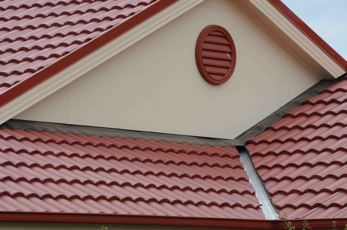
Section 9: Flashings & Damp-Proof Courses (DPC)
How your walls stay dry — and why getting flashing and DPC installation right is essential
Moisture is the silent killer of homes. It can creep into walls, rot timber, rust metal, and cause all kinds of hidden damage. Flashings and DPCs (damp proof courses) protect your home from water ingress and rising damp. They’re non-negotiable components of compliant masonry construction, especially around openings and penetrations.
Minimum Requirements & Technical Details
📘 Standards Referenced:
- AS 3700 – Masonry Structures
- AS 4773.2 – Masonry in Small Buildings – Construction
- AS/NZS 2904 – DPCs and Flashings
Key Flashing & DPC Rules
🧱 Location of Flashings:
- Above window and door openings
- At roof/wall junctions
- Behind cladding interfaces
- At base of walls near slab edge or subfloor junctions
💧 DPC Installation Requirements:
- Must extend across the full width of the wall
- Must be placed at least 150 mm above ground level (or 75 mm above paved surfaces)
- Must not bridge cavities and should drain moisture to the outside
- Laps in DPCs or flashings must be a minimum of 150 mm and sealed or shingled to shed water
🪟 Cavity Flashings:
- Must include end dams (turn-ups at ends) to prevent water tracking sideways
- Should direct water to weep holes placed at the correct spacing (max 1200 mm apart typically)
- Must be visible at the base — not hidden behind mortar
Common Mistakes on Site
🚫 DPCs installed below slab edge or bridging cavity/no minimum clearance maintained
🚫 Flashings that are too short, improperly lapped, or missing turn-ups
🚫 Weep holes blocked or spaced too far apart
🚫 No DPC under window or door frames
🚫 Incompatible materials (e.g. PVC flashings not suited to UV exposure)
Inspection Tips
🔍 Check that all DPCs and flashings are installed before brickwork continues past those points
🔍 Confirm visibility and positioning of DPC at base of walls
🔍 Look for signs of improper laps, gaps, or bridging across cavities
🔍 Check manufacturer data for flashing compatibility with cladding or render systems
NOTE: It should always be clearly visible on the outside of your walls—even after rendering (yep, how many homes have you seen with that detail?)
🧱 Section 10: Subfloor Construction
Subfloor construction is all about what’s happening between your home’s suspended floor and the ground underneath. It may not be something you see every day, but getting this part right is essential for ventilation, moisture control, termite prevention, and long-term durability.
Here’s what to look out for when inspecting the subfloor:
✅ Clear of Obstructions
- The space under the floor must be cleared of all building debris and vegetation. Anything left behind can trap moisture or provide food for termites—two things you definitely don’t want under your home.
🌬️ Cross-Ventilation Requirements
- The subfloor must be cross-ventilated with evenly spaced openings (as per Clause 6.2 of AS4773.2).
- These openings prevent “dead air” pockets that can lead to damp or mould issues.
⚠️ No Dead Air Spaces
- The area should be free from blocked zones. Good airflow must reach all parts of the subfloor.
📐 Minimum Ground Clearance (per AS 1684 & AS 2870)
Clearance between the ground and the underside of the lowest horizontal structural member is critical to ensure good ventilation and access for termite inspections.
- 400mm minimum between the ground and the underside of bearers over at least 90% of the subfloor area.
- 150mm minimum clearance is acceptable only in areas within 2m of external walls, usually on sloping sites, and only if the area is not intended for access.
- Ventilation openings in perimeter walls should be spaced to allow adequate crossflow—commonly 7500 mm² per metre of wall length (e.g., 230 x 110 mm weep hole bricks every 1.5m).
🌧️ Damp Sites and High Water Table Areas
If the ground is prone to dampness or flooding, the checklist provides three options to mitigate risk:
- Increase subfloor ventilation by 50%
- Install an impervious membrane (like a polythene ground sheet)
- Use treated timber – Durability Class 1 or 2 hardwood, or H3 preservative-treated softwood (as per AS1684)
Common Site Issues
🚫 Bearers not fully seated on stumps or piers
🚫 Inadequate nailing or missing joist straps
🚫 Clearance too tight — especially in corners or over plumbing
🚫 Water pooling under subfloor due to poor site drainage
🚫 Footings too small or shallow in reactive clay soils
Inspection Tips
🔍 Bring a tape — confirm 400 mm clearance to natural ground under bearers
🔍 Look for continuity of ant caps, and signs of timber exposure to water
🔍 Check for unbraced or wobbly subfloor supports
🔍 Confirm frame layout matches plans — including span direction and opening locations
S11: Sub Floor Ventilation
Why airflow matters — and what to check to keep your subfloor dry and healthy
Subfloor ventilation is often overlooked but plays a huge role in preventing timber rot, mould, and termite risk. It helps keep the underside of your home dry and safe, especially in Australia's varied climates.
Minimum Requirements & Technical Details
📘 Standards Referenced:
- AS 3660.1 – Termite Management
- NCC Volume Two – Housing Provisions
- AS 3959 – Construction in Bushfire-Prone Areas (if applicable)
Key Checks for Subfloor Ventilation
💨 Crossflow Ventilation
- Openings must be provided on opposite sides of the subfloor to allow for cross ventilation
- The minimum ventilation opening area must be:
- 7300 mm² per metre of wall length (as per NCC Vol 2, Part 3.4.1)
- May need to be increased in high humidity zones or where access is restricted
🌪️ Unobstructed Airflow
- Vents must be above ground level and not blocked by soil, landscaping, or decking
- Avoid placing vents too low, where leaf litter or stormwater runoff can clog them
- Check that internal footings or dwarf walls do not block airflow
🛠️ Vent Types and Materials
- Vents can be brick, metal, or plastic
- Must be vermin-proof and corrosion-resistant
- In bushfire-prone areas, vents may need metal mesh with a max aperture of 2 mm
Common Site Issues
🚫 Vents installed only on one side — no crossflow
🚫 Blocked vents due to soil build-up or cladding overhang
🚫 Landscaping too high — covering or restricting airflow
🚫 Lack of ventilation under decks, especially where they wrap around the home
🚫 No consideration of airflow paths — vents blocked by internal subfloor walls or services
Inspection Tips
🔍 Count the number of vents per wall and check spacing
🔍 Look for signs of condensation or dampness under the home
🔍 Confirm vents are not painted shut or covered over with cladding
🔍 In bushfire areas, check for compliant ember-resistant screens (weepa guards is one type of void former/spark protector product).
Section 12: Subfloor Piers
Getting your piers right — foundation support and spacing rules that matter
Subfloor piers are the upright supports that carry the load of your floor framing down into the ground. Whether they’re made of brick, block, or concrete, they need to be built right to ensure your home stays level, safe, and structurally sound.
Get your piers right, and the rest will follow. Be colour blind, dont be so shallow (Envogue on mind again).
Minimum Requirements & Technical Details
📘 Standards Referenced:
- AS 2870 – Residential Slabs and Footings
- AS 3700 – Masonry Structures
- NCC Volume Two – Housing Provisions
Key Checks for Subfloor Piers
🧱 Materials and Construction
- Must be constructed of solid masonry (brick or concrete block), reinforced concrete, or precast concrete stumps
- Mortar joints must be full and even — no dry-stacked blocks or unfilled joints
📏 Pier Spacing and Location
- Piers should be spaced and positioned according to engineering design
- Typically spaced under bearers, junctions, and point loads
- Common spacing is every 1800 mm – 2100 mm, but this varies depending on floor loads and bearer sizes
🧩 Footing Support and Bearing
- Piers must sit on adequately sized footings, which are engineered to support the load
- Footings may be bored piers, pads, or strip footings — all depending on soil classification and design
- Minimum embedment depth and width must comply with AS 2870 and be suited to the site’s reactive clay class (e.g., Class H1, H2, etc.)
⚙️ Pier Height and Alignment
- Piers must be plumb, level, and spaced correctly
- All pier tops should align to provide an even bearing surface for bearers
- Any variation in pier height should be addressed using non-compressible packers (not timber wedges)
🪵 Bearer to Pier Connections
- Bearers must be tied down or fixed to piers to resist uplift (wind or flood-prone areas)
- Check for galvanised brackets or straps where specified
Common Site Issues
🚫 Piers set too far apart — leading to bouncing or sagging floors
🚫 Uneven heights — resulting in floor dips or squeaks
🚫 Poor mortar joints — leading to cracking or water ingress
🚫 Unsupported piers (no proper footing beneath)
🚫 Inadequate pier size for the load being carried
Inspection Tips
🔍 Count and measure pier spacing against the plans
🔍 Check alignment of pier tops with a string line or laser
🔍 Confirm footing type and size — ask for the engineering if unsure
🔍 Look for movement cracks or signs of water damage at the base
S13: Control Joints
Why planned breaks in your brickwork matter more than you think
Control joints are intentional vertical gaps built into masonry walls to manage shrinkage and prevent cracking. As brickwork dries and moves over time (due to temperature changes, moisture loss, and foundation/soil movement), these joints allow controlled expansion and contraction — rather than random, ugly cracks appearing in your walls.
Minimum Requirements & Technical Details
📘 Standards Referenced:
- AS 4773.2 – Masonry in Small Buildings – Construction
- AS 3700 – Masonry Structures
- NCC Volume Two – Housing Provisions
Key Requirements for Control Joints
📏 Maximum Spacing
- For standard clay masonry walls, control joints must be no more than 6 metres apart horizontally
- If the wall has openings (windows/doors), spacing may need to be reduced to 5 metres
- Joint spacing must be shown on the construction drawings
🏗️ Location Guidelines
- At large, uninterrupted wall sections
- Adjacent to returns, corners, or major openings
- Where different materials meet (e.g. between brick and block)
- At changes in wall height or thickness
🧱 Joint Construction
- A control joint is typically a 10 mm wide vertical gap filled with a flexible sealant and a compressible foam backing rod
- There should be no mortar in the joint
- Joint must extend full height of the wall or at least between slab and soffit
🌡️ Thermal and Moisture Considerations
- Control joints help manage movement caused by heat, cold, and moisture cycles
- Especially important in south or west-facing walls exposed to high temperature fluctuations
Common Site Issues
🚫 Joint not provided where needed — often forgotten in long walls
🚫 Mortar left in the joint — defeating the purpose
🚫 Poor quality sealant or no backing rod used
🚫 Joint not aligned with control joint in slab or frame
🚫 Builders confusing control joints with articulation joints (these serve different purposes — see next section)
Inspection Tips
🔍 Check plans and elevations for control joint locations — are they built as shown?
🔍 Measure wall lengths to confirm joints have been installed at correct intervals
🔍 Inspect sealant — it should be neat, flexible, and not sagging or cracking - 2:1 width to depth ratio is best for lowest modulus (highest expansion of sealant).
🔍 Look for signs of cracking near areas where joints were missed or incorrectly placed
S14: Articulation Joints
Keeping your brickwork from cracking as your house settles
Articulation joints are vertical movement joints in masonry walls that allow for differential movement — that is, movement between different parts of the structure. These joints are essential in areas where footings, slabs, or frames may settle or move differently, such as at building corners, junctions, or beside large openings.
While control joints manage shrinkage in the brickwork itself, articulation joints accommodate movement in the structure supporting the brickwork. Both are vital, but serve different purposes.
Minimum Requirements & Technical Details
📘 Standards Referenced:
- AS 4773.2 – Masonry in Small Buildings – Construction
- NCC Volume Two – Housing Provisions
Key Requirements for Articulation Joints
📏 Spacing and Placement
- Max horizontal spacing: 6 metres
- Required:
- At wall returns (corners)
- At junctions between dissimilar materials or different footing types
- Adjacent to large openings (e.g. windows and doors)
- Where wall height changes significantly
- At changes in slab level or step-downs
- Between attached structures (like garages or verandahs)
🧱 Joint Construction
- Typically 10 mm wide, formed during bricklaying
- Filled with a flexible sealant over a compressible backing rod
- Must extend from DPC (damp-proof course) to the eaves or soffit
🛑 Important:
There must be no ties or mortar bridging the joint. These can transfer movement and cause cracking.
Common Site Issues
🚫 Joints missing at structural junctions (e.g. garage-to-house walls)
🚫 Mortar left in joints — completely defeats the purpose
🚫 Bricks too tightly spaced — no allowance for movement
🚫 No articulation joint on corners of long walls
🚫 Incorrect sealant or backing material used
Inspection Tips
🔍 Check against architectural and structural plans — are joints located where they’re supposed to be?
🔍 Look for cracking near windows, corners, and step-downs — signs that articulation joints may be missing
🔍 Confirm no bridging ties, reinforcement, or mortar exists within the joint
🔍 Sealant should be flexible, continuous, and not separating from either face
S15: Contraction + Expansion Joints
Managing the natural movement of masonry due to temperature and moisture changes
Contraction and expansion joints are used to control movement that results from thermal expansion, moisture changes, or shrinkage in building materials — especially in long or exposed walls. These joints reduce the risk of unsightly or structural cracking and are required, where temperature swings and moisture variation are common.
Minimum Requirements & Technical Details
📘 Standards Referenced:
- AS 4773.2 – Masonry in Small Buildings – Construction
- NCC Volume Two – Housing Provisions
Types of Joints
- Expansion Joints
- Allow bricks to expand with heat or moisture
- More common in clay bricks, which absorb moisture and grow over time
- Contraction Joints
- Allow materials to shrink without cracking
- Common with concrete masonry, which tends to shrink as it dries
🧱 Joint Width
- Typically 10 mm wide
- Extend from DPC to top of wall (soffit or eaves)
- Must be filled with flexible sealant over compressible backing rod
Placement Rules
📏 Maximum spacing guidelines:
- For clay bricks: every 6–7 m (varies by exposure and wall height)
- For concrete blocks: every 4.5–6 m
📌 Required:
- At changes in direction (corners, returns)
- Beside large wall openings
- Between differing construction types or materials
- Where there are changes in footing type or slab step-downs
- In long straight runs of wall (especially north- or west-facing walls exposed to sun)
Common Site Issues
🚫 Joints omitted or poorly located
🚫 Bridging mortar or wall ties reducing flexibility
🚫 Sealant not used, or wrong type applied
🚫 No compressible backing rod behind sealant
🚫 Brick spacing too tight (joints not visible or functional)
Inspection Tips
🔍 Measure distances between joints — are they within code?
🔍 Check that joints are unobstructed and go from DPC to top plate or roof frame
🔍 Ensure no wall ties or mortar bridge the joint
🔍 Confirm the sealant is flexible, bonded to the sides (not back), and not cracked or peeling
While were channeling our 90's memories, heres another to keep you going through the post:
S16: Tying Across the Cavity
Ensuring structural stability and safety with proper wall tie installation
Wall ties are required in cavity wall (brick veneer) construction. They connect the brick outer skin to the timber or steel frame (or to another leaf of masonry), allowing the two layers to act together while still moving independently enough to cope with shrinkage, expansion, and wind loads.
When wall ties are installed incorrectly — or missing entirely — it can lead to severe cracking, bulging walls, and structural instability, especially under high wind pressure.
Minimum Requirements & Technical Details
📘 Standards Referenced:
- AS 4773.2 – Masonry in Small Buildings – Construction
- AS/NZS 2699.1 – Built-in components for masonry – Wall ties
Tie Types and Materials
✅ Material: Galvanised steel (minimum) or stainless steel in coastal or severe environments
✅ Types: Butterfly, rectangular, or wire ties (as specified by the designer)
🧱 Embedment Depth:
- Minimum 50 mm into the mortar joint of the masonry leaf
- Must not be “pushed in” after mortar starts setting
Spacing & Layout Requirements
📏 Standard Spacing:
- 600 mm horizontal x 450 mm vertical
- Additional ties within 300 mm of openings, intersecting internal walls, above and below floor levels and control joints
- Two ties per brick length around large windows or doors
🧱 Tie Orientation:
- Should slope downward towards the outer leaf to direct moisture into the cavity
- Positioned to avoid crossing control joints (unless using special movement ties)
Common Site Issues
🚫 Ties installed too late or pushed into dry mortar
🚫 Insufficient embedment depth or ties poking out of joints
🚫 Wrong tie type for the exposure zone
🚫 Ties not installed within required spacing
🚫 Bridging across expansion or control joints
Inspection Tips
🔍 Visually check tie installation before mortar sets
🔍 Pull-test a sample area (with builder's consent) to confirm embedment
🔍 Confirm that wall ties are not distorted, bent, or coated in mortar
🔍 Check manufacturer details if stainless steel is required (especially in coastal builds)
S17: Lintels + Arches
Supporting openings with structural confidence
Lintels and arches are essential elements in masonry construction. They span over window and door openings, transferring the load of the masonry above to the walls on either side. If not installed properly, lintels can sag, crack, or fail — leading to structural damage and expensive rectifications.
Minimum Requirements & Technical Details
📘 Standards Referenced:
- AS 4773.2 – Masonry in Small Buildings – Construction
- AS/NZS 2699.3 – Lintels and shelf angles
Lintel Installation Requirements
✅ Material Types:
- Galvanised steel, pre-fabricated steel angles, concrete, or timber (engineered only)
📏 Minimum Bearing:
- Lintels must have minimum 150 mm bearing onto masonry at each end
- Bearing should sit on full solid masonry units (not over joints or hollow bricks)
🧱 Protection Against Corrosion:
- All lintels must be corrosion-resistant — usually hot-dip galvanised or stainless steel in coastal or marine zones
- Must not be cut or modified on-site without structural engineer approval
📐 Installation:
- Installed level and plumb
- Ensure adequate mortar packing over lintels (avoid hollow spots that weaken load distribution)
- Fully built-in to the cavity wall with flashing over the top (especially above windows and doors)
Arches and Special Details
🧱 Arched Openings:
- Require formwork or arch bars during construction
- Loads must be directed to sides of the arch properly — poor geometry or uneven brick sizes can compromise strength
📏 Control Joints:
- Avoid placing control joints directly above lintels unless specified with movement-tolerant systems
Common Site Issues
🚫 Lintels installed with less than 150 mm bearing
🚫 Corrosion visible due to cuts, scrapes, or missing galvanising
🚫 Hollow masonry units used under lintels
🚫 Lintels not flashed properly — increasing the risk of water penetration
🚫 Arch bricks not cut consistently — causing poor visual finish and stress concentrations
Inspection Tips
🔍 Check that lintels are straight, level, and supported on solid brickwork
🔍 Look for visible corrosion or improper coating
🔍 Confirm that lintels are not bridging movement joints without allowance for movement
🔍 Ensure appropriate flashing is present over lintels, especially above openings
Which song best represents being well supported?
S18: Brick Veneer Walls
Understanding veneer construction and cavity integrity
Brick veneer is one of the most common cladding methods in Australian residential construction. While it gives the appearance of a full brick home, it’s actually a non-loadbearing outer skin fixed to a structural timber or steel frame. The key to a long-lasting brick veneer wall is good detailing — especially the cavity and wall tie placement.
Minimum Requirements & Technical Details
📘 Standards Referenced:
- AS 4773.2 – Masonry in Small Buildings – Construction
- AS 3700 – Masonry Structures
- NCC Volume 2 – Housing Provisions
Brick Veneer Wall Requirements
✅ Cavity Clearance:
- Minimum 40 mm between the back of the brickwork and the external face of the wall frame
- Must remain clear and unobstructed for water drainage and airflow
- Cavity must not be bridged by mortar droppings or debris
📏 Brick Thickness:
- Standard clay brick width: 110 mm
- Total veneer wall thickness (brick + cavity + cladding or wrap): ~160–180 mm
🔩 Wall Ties:
- Must be corrosion-resistant
- Spaced no more than 600 mm horizontally, 450 mm vertically
- Ties must slope downwards and outwards (towards the brick)
- Embedment: 50 mm min into the mortar joint of the brick
🧱 Bottom of Veneer:
- Weep holes must be provided every 1.2 m above the slab or flashing
- Veneer must not be in contact with the ground
🪵 Timber Frame Movement:
- Timber shrinkage or frame movement must be allowed for — particularly around windows and doors
- Use control or articulation joints to avoid cracks forming in the veneer
Common Site Issues
🚫 Cavity blocked with mortar droppings or debris
🚫 Ties not properly embedded or angled
🚫 Bricks hard up against the timber frame (no cavity)
🚫 Inadequate or missing weep holes
🚫 Poor brick alignment or inconsistent joint widths
🚫 Shrinkage cracks appearing due to missing articulation joints
Inspection Tips
🔍 Confirm cavity depth and check for bridging with a mirror or cavity camera
🔍 Inspect wall tie placement, spacing, embedment, and orientation
🔍 Check bottom course for correct weep hole spacing and proper flashing
🔍 Ensure articulation joints are installed where specified (usually every 6 m or less)
🔍 Verify that the brick veneer sits above finished ground level — typically at least 150 mm above soil or paving
S19: Damp Proof Courses, Flashings + Weep Holes
Keeping your walls dry and protected from rising moisture and leaks
This section covers three critical elements that work together to manage water in brick veneer and double brick construction — the DPC (Damp Proof Course), flashings, and weep holes. Each serves a role in redirecting moisture and preventing long-term damage to your structure.
Minimum Requirements & Technical Details
📘 Standards Referenced:
- AS 3700 – Masonry Structures
- AS/NZS 2904 – Damp-proof Courses and Flashings
- NCC Volume 2 – Housing Provisions
Damp Proof Courses (DPCs)
✅ Purpose:
- Stops rising damp by creating a waterproof layer
- Typically a plastic membrane, bitumen sheet, or metal flashing
📏 Installation Rules:
- Laid horizontally in the mortar bed, above slab edge or footing
- Must extend full width of the wall
- Should turn downwards at the face to direct moisture out
- Minimum height:
- 150 mm above finished ground level (external walls)
- 75 mm above paved surfaces
🧱 In Brick Veneer Walls:
- Often installed above the slab rebate
- Can sit under windows, doors, and sill flashings
Flashings
✅ Purpose:
- Direct water out of cavities, preventing it from soaking into framing or internal walls
- Placed over openings, lintels, sill areas, and junctions
📏 Key Points:
- Must be waterproof, flexible, and durable
- Should overlap with the DPC in some locations to maintain continuity
- Extend to the face of the wall where water can escape
- Often visible under sill bricks or above windows and doors
🧰 Common Flashing Materials:
- Polyethylene sheeting
- Bitumen-based membranes
- Lead or aluminium (less common in resi construction now)
Weep Holes
✅ Purpose:
- Let water drain from the cavity to the outside
- Provide ventilation to help the cavity dry out
📏 Spacing Requirements:
- At maximum 1200 mm centres
- Should be located:
- Immediately above DPCs and flashings
- Above all wall openings (windows, doors, lintels)
- At the base of brickwork walls
🪟 Size & Design:
- Must be at least diameter of a 10 mm hole
- Can be formed using plastic inserts (e.g., Weepa products), gaps in mortar joints, or proprietary vents
🔥 Bushfire Areas:
- In BAL-rated zones, metal mesh (≤ 2 mm aperture) is required to prevent ember attack
- Weepa’s BAL-rated inserts are often used here
Common Site Issues
🚫 DPCs folded back or not turned down at edges
🚫 Flashings cut short or not lapped properly
🚫 Weep holes missing or blocked by mortar
🚫 Incorrect spacing or placement of weep holes
🚫 DPCs not extending across the full wall thickness
Inspection Tips
🔍 Check that DPC is installed in the correct mortar bed, visible where required
🔍 Confirm flashings are continuous, turned down at the face, and exit to daylight
🔍 Measure the spacing of weep holes and inspect for blockage or obstruction
🔍 In bushfire areas, ensure weep hole inserts meet BAL requirements
🔍 Look for signs of dampness, staining, or efflorescence that could indicate poor water management
S20: Cavity Flashings
Protecting your wall cavity from hidden water damage
Cavity flashings are installed to direct water that enters the cavity out of the building — before it can cause damage to internal wall linings, insulation, or timber framing. This section focuses on how cavity flashings should be installed in brick veneer or cavity brick construction to meet both durability and performance standards.
Minimum Requirements & Technical Details
📘 Standards Referenced:
- AS/NZS 2904 – Damp-proof Courses and Flashings
- AS 3700 – Masonry Structures
- NCC Volume 2 – Housing Provisions
Purpose of Cavity Flashings
✅ Key Role:
- Captures water running down the inside of the brick outer skin
- Redirects it back out through weep holes or weep vents
- Prevents moisture entering the timber frame or internal finishes
🧱 Installed at:
- The base of cavity walls
- Over penetrations (windows, doors, meter boxes)
- Over lintels, and behind wall junctions
- At floor level changes or where the cavity is bridged
Installation Requirements
📏 General Rules:
- Flashing must extend across the cavity and return upwards behind the internal wall or membrane
- Must turn down at the face of the wall and extend to weep holes
- Should lap with DPC to form a continuous waterproof barrier
- Must be durable, waterproof, and installed to slope toward the exterior
- Can be fixed to framing or built into the mortar bed depending on location
🧰 Materials:
- Polyethylene or polypropylene sheeting
- Bituminous or rubberised flashings
- Metal (aluminium, lead, copper – used less often in housing)
Common Issues on Site
🚫 Flashing doesn’t extend far enough into or across the cavity
🚫 No downward turn at the face — water can’t escape
🚫 Flashing is folded back into the wall or missing entirely
🚫 Not lapped correctly with DPC or building wrap
🚫 Weep holes not aligned with flashings
Inspection Tips
🔍 Check that cavity flashings are installed at the base of all cavity walls
🔍 Look above doors, windows, meter boxes and wall junctions for proper flashing
🔍 Confirm that flashings exit at weep holes and turn down to shed water
🔍 Ensure flashings aren’t cut, torn or punctured
🔍 Test for continuity with DPCs and building wraps — there should be no gaps or breaks
S21: Sill Flashings
Keeping water out from under your windows
Sill flashings are installed under window and door frames to collect and drain water that may leak past the frame or be driven by wind. Without proper sill flashings, moisture can enter the wall cavity and lead to rot, mould, or internal wall damage.
Minimum Requirements & Technical Details
📘 Standards Referenced:
- AS/NZS 2904 – Damp-proof Courses and Flashings
- NCC Volume 2 – Housing Provisions
- Window Installation Guidelines (AFRC & AWA)
Purpose of Sill Flashings
✅ Catch water that may leak through or around the window frame
✅ Redirect it outward through weep holes in the brick veneer
✅ Protect the wall cavity and framing from moisture damage
🔁 Often used in conjunction with:
- Back flashings or tapes behind the window
- Side flashings that return up the jambs
- Membrane wraps integrated into the wall system
Installation Requirements
📏 General Rules:
- Sill flashings must slope toward the exterior (a fall of approx. 15° is ideal)
- Must extend beyond the window opening (min. 150 mm either side)
- Should lap into the cavity and turn down at the external face
- Must align with and discharge through weep holes
- Jamb flashings or sealing tapes should overlap the sill flashing for continuity
🧰 Common Flashing Types:
- Preformed rigid plastic trays
- Folded sheet metal (aluminium or stainless steel)
- Flexible membranes (bituminous, polyethylene, or EPDM)
Common Issues on Site
🚫 Sill flashings installed flat or sloping inwards
🚫 No end dams — water leaks sideways into the frame
🚫 Flashing doesn’t connect with weep holes
🚫 Membrane wrap is cut short and not integrated
🚫 Gaps or voids between window frame and flashing
Inspection Tips
🔍 Check that sill flashings:
- Extend well past the window opening on both sides
- Slope outward to drain water
- Turn down at the external face and reach the brick veneer
- Are integrated with the building wrap or sarking
- Have no visible damage, folds, or reverse slopes
🔍 Look inside the cavity (if accessible) to verify correct laps
🔍 Confirm water exits cleanly through weep holes
S22: Wall Ties
Holding your brickwork and frame together—safely
Wall ties are the unsung heroes of brick veneer construction. They connect the outer brick skin to the inner timber or steel frame, ensuring the structure behaves as one unit and can safely resist wind loads and other forces. Poor tie placement or missing ties can lead to serious structural issues like cracking or even brick wall collapse.
Minimum Requirements & Technical Details
📘 Standards Referenced:
- AS 4773.2 – Masonry in Small Buildings
- NCC Volume 2 – Housing Provisions
Types of Wall Ties
🧱 Common tie types used in brick veneer include:
- Butterfly ties (wire, V-shaped)
- Flat ties (stamped sheet metal)
- Brick ties with drip edges (to prevent water tracking)
Ties must be corrosion resistant—typically made from stainless steel or galvanised steel depending on the exposure environment.
Spacing & Placement Rules
📏 Standard Spacing:
- 600 mm horizontal x 450 mm vertical spacing
- Within 300 mm of all openings, placed no more than 300 mm apart vertically (often referred to as "double ties" around windows and doors)
- Embedment into mortar bed must be 50 mm minimum
- Must be bedded solidly in mortar and not left floating
🛠️ Installation tips:
- Ensure ties slope slightly downwards towards the brickwork (to direct any water away from the frame)
- Do not bend ties excessively—this weakens the metal and reduces effectiveness
- Use the correct tie for your wind classification and frame material
Common Problems on Site
🚫 Missing or insufficient number of wall ties
🚫 Ties floating in the cavity or not embedded in mortar
🚫 Ties installed flat or sloping toward the frame
🚫 Ties too close to wall edges or not within allowable distances
🚫 Corroded ties used in coastal or high-exposure areas
Inspection Tips
🔍 Check that:
- Ties are installed to the correct spacing in both directions
- Extra ties are placed around openings (windows/doors)
- Ties are embedded at least 50 mm into the mortar
- Ties are not bent excessively, and have correct orientation
- Materials are appropriate for the corrosion zone (e.g., stainless near the coast)
Use a torch and mirror (or camera) to spot ties in the cavity when brickwork is partially done.
S23: Roof Anchorage
Keeping your roof firmly attached in all conditions
Roof anchorage refers to the method used to tie the roof framing securely to the wall frame and masonry structure. This is especially important in areas subject to high winds or cyclonic conditions. Proper anchoring prevents the roof from lifting off during storms and ensures the building’s structural integrity.
Minimum Requirements & Technical Details
📘 Standards Referenced:
- AS 1684 – Residential Timber-Framed Construction
- NCC Volume 2 – Housing Provisions
- AS 3700 – Masonry Structures (for anchoring into masonry)
How Roofs Are Anchored
🏗️ Common roof anchorage methods:
- Metal strap ties or cyclone ties wrapping over top plates and secured into trusses
- Threaded rods embedded into masonry or connected to tie-down rods running through the frame
- Proprietary brackets or connectors (e.g., triple grips, tie-down clips) for specific truss and rafter designs
🧰 Anchorage is typically achieved by:
- Connecting trusses or rafters to top plates
- Anchoring top plates to studs and wall framing
- Anchoring wall framing to the slab or subfloor structure
All connections form a continuous load path from roof to ground.
Wind Ratings & Anchor Selection
🌪️ Your roof anchoring method must match the site’s wind classification (e.g., N1 to N4, C1 to C4 for cyclonic areas). The higher the wind rating, the stronger the anchorage system required.
🛑 Using under-rated or insufficient anchorage hardware is a compliance failure and a safety risk.
Common Problems on Site
🚫 Incomplete or missing tie-downs
🚫 Loose fixings or nails instead of specified screws/bolts
🚫 Brackets or straps not nailed off correctly (or missed entirely)
🚫 No continuity from trusses to slab (breaks in the load path)
🚫 Incorrect brackets used for wind rating or frame type
Inspection Tips
🔍 Look for:
- Correct type of anchors for your wind rating and construction type
- Secure fixings at every connection point — truss to top plate, plate to studs, and studs to slab
- No missing straps, bolts, or brackets
- Anchorage system follows the engineer's design and AS standards
- Roof Connected to the frame not to masonry walls (unless engineer designed to do so).
Pro Tip: Always check the builder’s tie-down schedule or engineering plans to verify that on-site install matches what's required.

Read more about timber framing here
Read more about timber framing and here
S24: Reinforced Walls
Strengthening walls with steel reinforcement
Reinforced masonry walls include embedded steel to increase their strength, especially in areas where high loads, lateral forces (like wind or earthquakes), or structural bracing is needed. These walls are common around garages, stairwells, boundary walls, and retaining walls, or wherever structural performance exceeds what unreinforced brickwork can handle.
Minimum Requirements & Technical Details
📘 Standards Referenced:
- AS 3700 – Masonry Structures
- NCC Volume 2 – Housing Provisions
What Makes a Wall Reinforced?
🧱 A wall is classed as reinforced when it contains embedded reinforcing steel bars (rebar) and grout-filled cores (usually in hollow concrete blocks or grouted brick cavities). These work together to resist tension, compression, and shear.
👷 Typical reinforcement elements:
- Vertical starter bars fixed into the slab or footing and extending into wall cores
- Horizontal bars placed in bond beams or cavities
- Grouted cores or cells to bond everything together
Key Installation Checks
🔩 Starter Bars:
- Must be correctly located and sized as per engineer’s specs
- Should extend fully into the wall core, with proper overlap (lap length typically ≥ 40 x bar diameter)
- 450mm minimum laps
🧱 Block/Brick Units:
- Units around reinforcement should have clean cores
- No mortar blockages that prevent grout flow
🧪 Grout:
- Should be a stiff but flowable mix, fully filling voids
- Vibrated or rodded into place to remove air pockets
🧰 Ties and Spacing:
- Reinforcement must be tied in place to prevent movement during grout pour
- Spacing must match engineer's plan and AS 3700
Common Issues to Watch For
🚫 Starter bars out of position or missing
🚫 Short laps or bars cut too short
🚫 Mortar slop inside cores, blocking grout
🚫 Poor grout placement or dry-pack instead of flowable mix
🚫 No evidence of inspection prior to grout pour
🚫 Clean out blocks not tied properly, grout spill out/cleanup/wasted
Inspection Pro Tip: Reinforced walls are often covered quickly. It’s important they are inspected before grout is poured (engineer signed off) and again after to check for visible cracks or misalignments.
S25: Cleaning of Masonry
The right way to clean brickwork without damaging it
Cleaning masonry might seem like the easy part — but it’s where a lot of good work gets ruined. If not done properly, cleaning can cause stains, surface damage, and long-term deterioration of mortar and bricks.
Minimum Requirements & Technical Details
📘 Standards Referenced:
- AS 4773.2 (Appendix B) – Masonry in Small Buildings: Construction
- CMAA Technical Note 9 – Cleaning Clay Masonry
Key Cleaning Guidelines
🧽 Timing Matters:
- Clean masonry only after mortar has cured — typically 7 days minimum
- Never clean while mortar is still green (soft) as this can cause streaking and mortar loss
💧 Water First:
- Pre-wet the wall with clean water to stop cleaning agents from soaking in and damaging the surface
- Always rinse thoroughly before and after using any cleaning product
🧴 Approved Cleaning Agents:
- Use proprietary masonry cleaners (mild acids) as recommended by the brick manufacturer
- Always test a small area first
- Avoid strong hydrochloric acid — it's too aggressive and can damage mortar joints and discolour bricks
⚠️ Avoid These Common Mistakes:
- High-pressure water cleaning (especially above 700psi) — this erodes mortar and can cause water ingress issues
- Dry scraping or wire brushing — this can scratch and permanently scar bricks
- Leaving acid on too long, or letting it dry on the wall
🧼 Tools That Work:
- Soft natural bristle brushes
- Low-pressure water rinse
- Diluted acid solution if needed (1 part acid to 10 parts water is a common dilution)
Additional Tips
🛑 Always check the manufacturer’s cleaning guide — different bricks (clay vs concrete) need different treatment.
🧱 Be extra cautious with coloured or textured bricks — they’re more vulnerable to damage.
🚧 Cleaners should be experienced and know how to safely handle chemical solutions.
S26: Site – Lock-Up – Access Doors – Sill & Handle Protection
How to protect your doors, sills, and hardware during construction
Lock-up is a key milestone, but damage can easily occur from careless handling, trades using doors before completion, or inadequate protection. This section ensures your site security and finishes stay intact.
Minimum Requirements & Technical Details
📘 Standards Referenced:
- AS 2047 – Windows and External Glazing
- Manufacturer installation guides for doors and hardware
- National Construction Code (NCC) – General access and egress provisions
Checklist for Inspection
🚪 Access Doors:
- Entry doors must be installed square, plumb, and operate freely
- No bowing, twisting, or gaps — especially at the head or sill
- Confirm compliance with the selected BAL (Bushfire Attack Level) rating where applicable
🔐 Locking & Hardware:
- Ensure locks and handles are operational, undamaged, and properly aligned
- Confirm striker plates are fitted securely — no loose fixings or misalignment
- Handles must be protected with coverings to avoid scratches or dings
🧼 Door Sill Protection:
- Door sills should be protected with tape or sill covers — especially aluminium thresholds
- No damage from construction traffic, bricks, or tools
- Timber thresholds must not be water damaged — check for swelling or cupping
🚧 Site Security at Lock-Up:
- All external doors must be lockable and closed securely overnight
- Ensure site fences or barriers remain in place for unauthorised access prevention
- Check that temporary garage doors or boarding are also secure and weather resistant
Common Issues to Watch Out For
- Missing or damaged sill protectors from early door installation
- Doors left open or unsecured after trades leave site
- Dirty, paint-splattered, or scratched handles and hardware
- Moisture exposure causing door swelling or frame movement
Take photos of your doors at lock-up. This helps track any damage that happens afterward and ensures warranty claims are clear-cut.
S27: General Inspection Items
Final checks before moving on — don’t skip these!
Even with every trade doing their part, small issues can slip through the cracks. This catch-all checklist helps ensure your masonry and cladding work meets expectations before progressing to painting or finishes.
Minimum Requirements & Technical Details
📘 Standards Referenced:
- AS 3700 – Masonry Structures
- AS 4773.2 – Masonry in Small Buildings
- Manufacturer specifications for flexible sealants, masonry tools, and finishes
Checklist for Inspection
🧱 Mortar Joints:
- Joints should be uniform, well-tooled, and 10 mm ± 3 mm
- No cracking, gaps, or messy smears
- Flush or ironed joints as per finish spec — not raked or rough unless intended
📐 Alignment & Plumb:
- Walls must be plumb, straight, and level — check across entire elevation
- Step-backs and overhangs should follow design specs with clean transitions
- Bond pattern consistent — especially important for face brick walls
📏 Cavity Clearances:
- Ensure minimum 50 mm cavity is maintained throughout
- No mortar droppings bridging across the cavity
- Cavity barriers or insulation (if required) should be properly installed
🕳️ Weep Holes:
- Spaced no more than 1200 mm apart, at lowest DPC level
- Free from mortar, clean and unobstructed
- Bushfire-prone areas must have compliant weep hole covers (e.g., Weepa)
🔍 Flexible Mastic Joints:
- Movement joints must be sealed with appropriate flexible sealant
- No shrinkage, cracking, or detachment
- Backing rod used where required to maintain proper joint profile
🧽 Clean-Up & Presentation:
- All excess mortar cleaned off surfaces
- No visible staining, efflorescence, or cement splatter on windows or frames
- Bricks washed down only with approved acid mix — not high-pressure water!
Common Issues to Watch Out For
- Inconsistent mortar thickness or tooling
- Weep holes blocked or installed too high/low
- Unsealed movement joints left open to the elements
- Efflorescence appearing due to poor moisture control
Walk the exterior with your builder using a checklist before painting starts. Once the scaffold is gone, fixes get more expensive — and harder to spot.
S28: Fibre Cement Cladding – Installation Generally
Getting the basics right for long-lasting, weatherproof walls
Fibre cement cladding is a popular choice for modern Australian homes. It’s durable, fire-resistant, and low maintenance — but only if installed correctly. This section covers the general requirements for installation before we get into finishes and framing specifics.
Minimum Requirements & Technical Details
📘 Standards Referenced:
- AS 2908.2 – Cellulose-Cement Products
- Manufacturer guidelines (e.g., James Hardie, CSR Cemintel)
- National Construction Code (NCC) Volume 2
Checklist for Installation
🔩 Fixing to Framing:
- Fibre cement sheets must be fixed to timber or steel frames with the correct fasteners (typically corrosion-resistant nails or screws)
- Minimum edge and end distances must be maintained to prevent cracking:
- 30 mm from sheet edges
- 50 mm from sheet corners
🧱 Sheet Layout and Jointing:
- Sheets should be staggered for structural integrity
- Gaps between sheets should follow manufacturer instructions (usually 5–10 mm) to allow for expansion
- Backing strips or proprietary joiners must be installed behind joints where required
🌧️ Weatherproofing:
- All penetrations must be sealed using flexible, UV-stable sealant
- Cladding must be installed with adequate overlap at horizontal joints
- Flashings must be installed at openings, base of wall, and all horizontal junctions to prevent water ingress
📏 Ventilation & Clearances:
- Bottom edge of cladding must maintain a minimum clearance of:
- 75 mm from finished ground level
- 50 mm above paved or concrete areas
- 25 mm above flashing
- Ensure bottom sheet is not submerged in soil or mulch
Common Issues to Watch Out For
- Sheets hard-fixed without expansion gaps (leads to cracking)
- Poor flashing details at windows or base of walls
- Incorrect fastener material, type/corrosion resistance, spacing or missing fasteners
- Overdriven nails/screws causing surface damage
Ask your builder which brand of fibre cement cladding is used — then check the manufacturer’s guide. It’s your go-to reference if something doesn’t look quite right.
S29: Fibre Cement Cladding – Installation – Finishes
Why how it’s finished makes all the difference
Once fibre cement sheets are installed, the finishing process ensures the cladding performs as intended — resisting weather, staying looking sharp, and lasting for years. Poor finishes can lead to cracking, moisture ingress, and early failure of the system.
Minimum Requirements & Technical Details
📘 Standards Referenced:
- AS 2908.2 – Cellulose-Cement Products
- Manufacturer installation and finishing guides (e.g. James Hardie, CSR Cemintel)
- NCC Volume 2 – Waterproofing and cladding requirements
Checklist for Finishes
🎨 Painting and Coating:
- All fibre cement products must be painted or sealed with an exterior-grade coating system
- Primer coats must be applied before final coats unless using pre-primed boards
- Use paint systems with minimum two-coat finishes suitable for fibre cement
- Must be painted within 90 days of installation (James Hardie products TDS)
💧 Sealing Joints and Penetrations:
- All cut edges, penetrations (e.g. pipes, vents), and joints must be sealed with manufacturer-recommended sealants
- Use PU (polyurethane) or MS polymer sealants that can flex and withstand UV exposure
🔍 Surface Preparation:
- Clean all surfaces before painting — no dust, oil, or moisture
- Fill any gaps, cracks or fastener holes with fibre cement-compatible fillers
🔨 Fastener Finishing:
- Countersunk screws or nails should be filled and not left exposed
- Finish must be smooth and flush to the cladding surface before painting
Common Issues to Watch Out For
- Failing to seal cut sheet edges (a major cause of water ingress)
- Using the wrong type of paint — internal acrylic won’t survive external conditions
- Gaps in sealant or missed fastener holes
- Not allowing enough curing time between primer and topcoat
✅ Tip for New Homeowners:
If your builder uses pre-primed cladding, make sure you or your painter still follow up with the correct finish system — these primers aren’t designed to be left exposed.
S30: Fibre Cement Cladding – Installation – Framing
It all starts with the right frame behind the board
The strength, durability, and straightness of fibre cement cladding depends heavily on how well the framing behind it has been built. Get this wrong, and you risk bowed sheets, popped fixings, water leaks, and long-term structural headaches.
Minimum Requirements & Technical Details
📘 Standards Referenced:
- AS 1684 – Timber Framing Code
- AS/NZS 1170 – Structural Design Actions
- Manufacturer framing guides for cladding products (e.g. James Hardie, CSR Cemintel)
Framing Checklist
🪚 Timber and Steel Frame Suitability:
- Timber must be straight, dry, and appropriately treated (H2 minimum for internal walls, H3 for external)
- Steel framing must comply with relevant corrosion resistance standards, especially in coastal areas
📏 Stud Spacing (Frame Centres):
- Typically 450mm centres for vertical installation
- 600mm centres may be acceptable for some thicker boards – check the cladding manufacturer’s data sheet
📐 Frame Alignment and Flatness:
- All framing must be plumb and true within 3mm over 1.8m
- No bowed or twisted studs – irregular framing leads to wavy cladding
🔩 Fixing Grounds:
- Install noggings, battens or back blocking where required to support sheet edges and penetrations
- Openings such as windows and doors must have adequate framing for flashing and fixing
💧 Moisture Management:
- Install wall wrap (pliable membrane) or building membrane that meets panel manufacturer minimum requirements behind cladding
- Make sure wraps are taped and sealed around windows, penetrations, and base of wall
Common Issues to Watch Out For
- Inconsistent stud spacing leading to unsupported joints
- Missing or misaligned noggings causing fixings to miss
- Incorrect stud sizing
- Moisture-sensitive timber not adequately treated
- Failing to allow for movement at floor junctions or slab edges
- Incorrect clearance from ground level, pathways, no termite inspection zone
Inspect your cladding for any visible bowing or bulging—these are often signs of an uneven frame or improperly secured fixings.
While checking the frame (including studs and walls for plumb and straightness) can be time-consuming, it’s worth the effort. A properly aligned frame ensures a solid foundation for everything that follows.
What were after before installing any cladding is straight lines (straight edge) - without deviations, bumps or distortions greater than 4mm
S31: Fibre Cement Cladding – Installation
Getting boards on the wall the right way
Now that the frame is correct, it’s time to install the fibre cement boards — and this is where attention to detail pays off. Fixing boards properly means fewer cracks, better waterproofing, and a cleaner finish overall.
Installation Best Practices
🧰 Fixing Methods – Screws, Nails, or Clips?
- Stainless steel nails or galvanised screws are typically recommended
- Always follow the cladding manufacturer’s instructions – some systems (like James Hardie’s Scyon) require specific proprietary fasteners
- Avoid overdriving fixings – they should be flush, not recessed
- Use corrosion-resistant fasteners, especially in coastal or high-humidity zones (refer to AS 2312 for corrosion zones)
📏 Fixing Spacing Guidelines
- Fixings are usually spaced at 200mm centres along sheet edges, and 300mm centres to intermediate studs
- Fix at minimum 12mm from sheet edges, and 50mm from sheet corners
- For vertical installation, joints must align with framing (do not join over empty space)
🔩 Sheet Joints – Butt or Rebate?
- Most systems use expressed joints or rebated shiplap joints
- Joints must be backed by continuous support battens or studs
- Use proprietary backing strips or sealant strips behind joints for weather resistance
- Apply a compatible sealant if joint requires sealing (check manufacturer spec)
💧 Weatherproofing Measures
- All vertical joints must be weather-sealed with appropriate tapes or sealants
- Ensure flashings are installed at penetrations (lights, taps, vents), vertical joints, and at base of wall
- Avoid joining sheets directly over floor joists – allow movement between floors
Movement Gaps & Expansion Allowance
🧱 Leave movement joints every 4.8m or as specified by manufacturer
- Provide minimum 5mm expansion gap between sheets (unless tongue & groove system is used)
- Gaps must be sealed or covered depending on cladding type
Common Issues to Watch Out For
- Sheets installed without enough clearance from ground or paving
- No gap left at sheet joins or incorrect joint treatment
- Fixings driven too deep or outside of specified zones
- Installation out of level or out of plumb
- Sheets touching slab edge or brickwork causing potential water ingress
Run your hand over the wall once the boards are up — it should feel smooth and even. If you notice steps between sheets or popping nails, it might signal poor fixing or uneven frame work underneath.
What we dont want in wall framin prior cladding - no humps 😄 - shit i get bored on fridays!
S32: Fibre Cement Sheet Cladding – Installation
Flat sheet cladding needs flat framing, detailed joints, and proper waterproofing
This section focuses specifically on flat fibre cement sheet cladding like James Hardie Villaboard, Blueboard, or similar products, commonly used under render or paint finishes.
Fixing and Jointing Requirements
🧱 Fixing Into Framing
- Fix sheets to timber studs (min 45mm wide) or steel framing (min 0.55mm BMT)
- Sheet edges must land on framing — never join over gaps
- Use corrosion-resistant nails or screws suitable for fibre cement products
- Typical fixing spacing:
- 200mm centres along edges
- 300mm centres on intermediate studs
- Minimum 12mm from sheet edge, 50mm from corners
🧰 Joint Treatment – Render Systems vs Expressed Joints
- For rendered systems (e.g., Blueboard):
- Apply alkaline-resistant fibreglass mesh over joints
- Use polymer-modified render basecoat as per system specs
- Follow up with finishing coats to manufacturer guidance
- For expressed joint systems:
- Use proprietary backing strips or control joint profiles
- Expansion gaps (usually 5mm) must be maintained and sealed if required
Control & Movement Joints
📏 Spacing and Placement
- Provide vertical movement joints every 5.4m max or as per manufacturer
- Also install joints:
- At internal corners
- At junctions with different materials
- Above or below large openings (e.g. windows/doors)
Clearances and Sealing
💧 Minimum Clearances
- 50mm above paving
- 75mm above soil or landscaped surfaces
- 150mm in high-exposure zones or where garden beds may build up
- 10mm clearance to flashings and horizontal surfaces
🛠️ Seal All Penetrations and Edges
- Around windows, pipes, and vents
- Use flexible, paintable sealant that’s compatible with fibre cement
- Ensure top edges and horizontal joints are sealed to prevent water tracking
Common Problems to Watch For
- Fixings missed framing – this causes long-term movement and cracking
- Inadequate joint mesh or render detailing
- Poor edge sealing, especially near penetrations
- No allowance for expansion — sheets may bulge or crack over time
- Insufficient clearance at base of wall leading to water wicking or termite risk
If you’re planning to paint over the sheets, ask the builder whether the sheets are “sealed” — fibre cement must be primed with an alkali-resistant primer before painting to avoid long-term paint failure.
Big takeaway from section 32 is - GROUND CONTROL - clearances! - great segway?
S33: Foam Cladding – Framing
Structural support matters – lightweight cladding still needs solid backing
Foam cladding systems (like EPS or XPS boards) are often used to create a rendered wall look with improved insulation. But despite being lightweight, they require careful and correct framing to ensure stability and prevent cracking.
Suitable Framing Materials and Fixing
🪵 Timber or Steel Framing
- Timber studs must be straight, treated (if external), and minimum 70mm wide
- Steel frames must be minimum 0.55mm BMT with adequate depth to support fixing screws
- All framing must be compliant with AS 1684 (timber) or AS/NZS 4600 (steel)
🔩 Fixings Must Meet System Specs
- Use approved fasteners that match the foam system (e.g. corrosion-resistant screws, plastic washers)
- Fasteners should not crush or over-compress the foam panel
Framing Requirements and Spacing
📏 Stud Spacing
- Max 600mm centres, unless system requires tighter spacing
- Nogging or blocking required at panel edges and junctions for support
- Always refer to manufacturer’s requirements — some systems may specify 400mm centres for added support
📐 Flatness is Critical
- Foam cladding must sit flush against the frame
- Any bulges, bows or gaps in the frame will show through once render is applied
- Use a straightedge or stringline across the wall face to check frame alignment before fixing panels
Moisture Considerations
💧 Breathability and Drainage Plane
- Some systems require a moisture barrier wrap or breathable membrane behind the foam
- Ensure appropriate weep paths and flashings are in place
- Check for proper drainage details at windows, doors and penetrations
Common Mistakes on Site
🚫 What to Avoid
- Skipping noggings, especially near windows and corners
- Fixing to bowed or out-of-plumb frames
- Ignoring manufacturer framing tolerances (which can lead to warranty issues)
- Allowing foam panels to span unsupported gaps or “float” over uneven substrate
If you’re ever on-site during cladding prep, ask to see the wall framing before the foam panels go up. A quick look with a level or straightedge can reveal problems before they’re hidden forever.
Typifying the 90's
S34: Foam Cladding – Fixing
How foam panels should be attached — and why missing this step can lead to system failure.
Foam cladding might look simple, but proper fixing is what keeps the system structurally sound and crack-free. If the panels aren’t fixed according to the system requirements, you risk delamination, bowing, or render cracking.
Fastener Types and Requirements
🔩 Approved System Fasteners Only
- Use manufacturer-specified screws, typically with plastic washers or fixing plates
- Fasteners must be corrosion-resistant (especially in coastal or marine zones)
- Some systems may allow adhesives in combination with screws — check the manual
📏 Spacing and Edge Distances
- Fixings are typically spaced at 300mm to 600mm centres
- Edge distances: Minimum 50mm from panel edges to prevent breaking
- Each panel must be fixed into studs or solid framing — not just into battens or bracing board
Fixing Technique
🛠️ Flush, Not Crushed
- Screws should sit snug with the surface, not over-tightened
- Over-driving screws compresses the foam, creating dips that show through render
🪵 Full Contact with Frame
- The panel must be in full contact with framing—no gaps, bulges or bowing
- If the frame is out of plumb, packers or shaving may be needed before fixing
Corners and Openings
🧱 Extra Fixings at Stress Points
- Provide additional fixings around windows, doors, and corners
- Foam must not bridge unsupported gaps — always fix to a solid substrate
- Corner beads and mesh are installed after fixing but depend on the panel being solidly fixed
Movement Joints
🌬️ Allow for Expansion and Contraction
- Install expansion joints in line with system specs
- These prevent render cracking due to temperature or structural movement
- Do not “butt-join” foam panels without joint allowance
Common Mistakes to Watch For
🚫 Incorrect Fixing Practices
- Fixing into bracing board instead of studs
- Using the wrong type of screw (e.g. standard plasterboard screws)
- Missing edges or corners, leaving the panel unsupported
- Not allowing for movement joints in long wall runs
If your builder says “we’ve done this a thousand times,” great — but ask if they’ve got installation guides for this exact system on-site. Foam cladding isn’t generic — it’s a proprietary system, and even small mistakes can void warranties.
Even better - say to them "show me your quality management (ITP - Inspection Test Plan, is part of this) and quaity control checklist (ITC) Inspection Test Checklist. Can i get a copy of the ITR (Inspection Test Report)?" Prove to me its installed correctly? - Show me, Show me the money!
S35: Foam Cladding – System Requirements
Why foam cladding is a system — and not just some boards and render stuck on a wall.
When we talk about foam cladding, we’re referring to a complete system — not just the foam panels. This includes how it’s fixed, sealed, meshed, coated, and painted. Everything must work together to ensure durability, thermal performance, and waterproofing. If you skip or swap components, you risk serious long-term damage.
🔒 System Accreditation & Compliance
- Foam cladding systems in Australia should be CodeMark certified or have an Alternative Solution approval.
- Certification ensures the product meets the National Construction Code (NCC) for use in external walls.
- Each system includes a detailed installation manual — this must be followed exactly, or the warranty and compliance are void.
📘 Key System Components
- Foam Panel (EPS or XPS)
- Expanded Polystyrene (EPS) is most common
- Typically 40–60mm thick, but can vary by manufacturer
- Must meet AS 1366 for thermal insulation boards
- Fixings + Washers
- Galvanised or stainless steel, per spec
- Plastic washers or fixing plates to distribute load
- Base Coat + Reinforcing Mesh
- Mesh embedded in base coat creates the first waterproof and crack-resistant layer
- Mesh must overlap at joins by 100mm minimum
- Top Coat / Render
- Acrylic or polymer-modified renders used
- Applied as a system — can’t swap brands or types halfway through
- Sealants + Expansion Joints
- Polyurethane sealants are required at joints, windows, and penetrations
- Expansion joints must be installed per system guide (typically every 5–6m)
- Primer + Paint
- Final protective coat, often with UV and water resistance
- Not optional — required to complete the system
🚨 Why This Matters
- Incorrect or partial installation voids warranties
- Incompatible products can lead to delamination, water ingress, or render failure
- Councils or private certifiers can issue stop work notices if a non-compliant system is identified (if they have staff and are actually looking).
👷 Common Site Issues
- Skipping mesh or using the wrong mesh type
- Using general render or paint not rated for EPS foam
- Fixing panels without checking the frame for plumb and straightness
- Missing expansion joints on long walls
- Rendering over wet or dirty foam panels, leading to poor adhesion
🧱 S36: Foam Cladding – Installation
This section outlines the installation requirements for foam cladding systems, also known as EIFS (External Insulated Finishing Systems). Foam cladding must be installed strictly according to the manufacturer’s approved system and must be supported by either a Codemark Certificate or an Alternative Solution that complies with the NCC (National Construction Code).
🔧 Key Inspection Items
- Installation to Manufacturer’s Details
Every component—foam boards, mesh, adhesives, fasteners, base coats, top coats, sealants—must follow the system’s approved manual or specification. No mixing and matching! - System Coverage
Ensure the system is complete. A proper foam cladding system includes:- Substrate preparation
- Adhesive or mechanical fixing
- Reinforcing mesh (embedded in base coat)
- Base coat layer(s)
- Top coat/render finish
- Sealants for all joints and terminations
- No Substitutions
All products used must be part of the certified system. Substituting adhesives, render, or sealants with other brands voids system compliance and may risk water ingress or failure. - Sealant Detailing
Use PU (polyurethane) sealants at all control joints, penetrations, window and door reveals, and wall junctions. These allow for flexibility and prevent cracking. - Ventilation Gaps
Some systems may require a ventilation gap between the foam board and the frame or substrate. Check the system manual—this is especially important in high condensation risk areas. - Fastener Spacing and Embedment
Where mechanical fixing is required:- Check fastener length (must fully penetrate the substrate or timber/steel framing)
- Spacing must match the system’s tested performance requirements
- All washers or fixing plates must sit flush and not over-compress the foam
- System Certification
Verify that:- The system is Codemark certified, or
- It has an engineered Alternative Solution confirming it meets the NCC performance requirements.
✅ Why It Matters
Foam cladding systems can fail catastrophically if incorrectly installed—leading to water ingress, rot, mould, or total render delamination. Ensuring the complete system is followed—not just parts of it—is the best protection.
🏁 Conclusion
Building a home is a huge investment, and while most people don’t have a builder’s license or years of site experience, when you have a clear and practical understadning of things, it puts power back in your hands.
This checklist is for every homeowner who wants their build done right. Knowing what to look for at each stage can help prevent costly defects, delays, or disputes later down the track.
Whether it's checking if the mortar’s been mixed properly or confirming your foam cladding system matches its certification, it’s all about clarity, confidence, and quality.
Use this guide to ask better questions, take better notes, and hold your builder accountable—because peace of mind is built, not promised.
📚 Yes, It Was a Beast of a Post—And That’s the Point
We know—this wasn’t a quick read. But building a home isn’t a 10-step checklist, and neither is making sure it’s done right. This blog post and our accompanying inspection checklist go deep—not just into one, but two key Australian Standards:
- AS 4773.2 masonry for small buildings
- AS3700 Masonry Structures
We’ve also unpacked a huge amount of detail around technical installation requirements, compliance documentation, and best practice site execution—the kind of things that often get skipped over in the rush to lock-up. This isn’t fluff. It’s not a repackaged “top 10 tips” blog. It’s here to help you understand what quality looks like on site, and why it matters.
If you sense frustration in our comments and posts, it’s because there is some. I genuinely don’t see or hear about builders prioritizing quality—just turnover. If you know of any who do, please tell me who they are. I’d love to give praise where it’s due.
Right now, it seems the residential sector is selectively applying—or outright ignoring—details while paying lip service to quality in the building process. Too often, craftsmanship and long-term durability take a back seat to speed and superficial "value."
This reflects a broader frustration with today’s culture: the half-hearted, inconsistent application of rules, summed up by the attitude of "good enough for you, but not for me."
Becuase you made it this far, congratulations! We could think of no better 90's music video to represent reaching the end of this marathon than.....Dr Alban.
FAQS
1. Do I need to inspect every item on this checklist myself?
Not necessarily—but it’s a good idea to understand what’s being checked so you can ask your builder the right questions. You can also engage a private building inspector to help you at key stages.
2. What’s the difference between mortar and grout?
Mortar is used to bond bricks together, while grout is used to fill in gaps or cavities, especially around reinforcement. Each has different mix requirements and purposes.
3. How do I know if a control joint is missing?
Control joints are usually vertical breaks in the brickwork that prevent cracking. They should be clearly visible at regular spacing, and particularly near long walls, windows, or doors.
4. Why is subfloor ventilation important?
Without proper ventilation, moisture can build up under your floor, leading to mould, timber rot, or even termite infestations. Minimum clearance and vent spacing are essential.
5. What should I look for in brick veneer construction?
Check for minimum cavity widths, proper tie placement, and that weep holes and flashings are installed—these prevent moisture from seeping into your home.
6. Is it okay for the builder to change the cladding material I picked?
Not without your written approval. All material and colour changes must be documented as variations—and you should check these against your original selections.
7. Can the builder use a different render or sealant than the one specified?
No. Foam and fibre cement systems rely on using matching, tested components. Substitutions can void warranties and lead to compliance issues.
8. What does 'Codemark Certified' mean for cladding systems?
It means the product has been tested and approved as meeting the NCC’s performance standards. If there’s no Codemark, your builder must have an Alternative Solution from a qualified professional. Composite decking boards is a product notorious for not having a codemark. Many imported products dont have a codemark. Some do, always check the product does or you may have an insurance issue in the event of a cliam related to this product.
9. Are wall ties really that important?
Absolutely! Wall ties hold your brickwork to the structural frame. Missing, misplaced, or improperly embedded ties can lead to serious structural failures over time.
10. Should I be worried about render cracking later on?
If movement joints were missed or poorly placed, cracking is almost guaranteed. Proper installation during this stage is critical to long-term durability and looks.
Further Reading