

Take The Quiz On This Post
Read the post, then take the quiz—test your knowledge and see what you’ve learned!
Introduction
Concrete foundations and slabs form the backbone of any residential house, providing the support needed to ensure the building’s stability and longevity. For many home owners, understanding the language and concepts of foundation and slab construction can seem overwhelming.
This blog post aims to demystify the process, offering you a detailed look into the components, design considerations, reinforcement details, and common terminology involved.
Whether you’re a home owner looking to build your dream home or someone interested in the construction process, this guide will provide you with insights into concrete foundations and slabs.
Section 1: Understanding Soil Conditions and Site Classification
1.1 Site Classification Based on Soil Reactivity
Before any construction begins, understanding the soil conditions on the site is very important. The type of soil directly influences the foundation design and construction approach.
In Australia, soils are classified based on their reactivity—how much they expand and contract with moisture changes.
This classification is essential because reactive soils can cause significant movement in foundations, leading to potential damage if not properly managed.
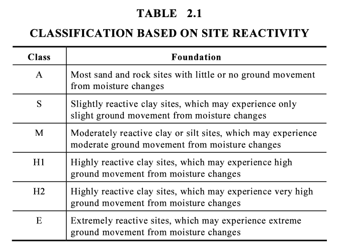
Soil reactivity is classified into several categories:
- Class A: Most sand and rock sites with little or no ground movement from moisture changes.
- Class S: Slightly reactive clay sites, which may experience only slight ground movement from moisture changes.
- Class M: Moderately reactive clay or silt sites, which may experience moderate ground movement from moisture changes.
- Class H1: Highly reactive clay sites, which may experience high ground movement from moisture changes.
- Class H2: Highly reactive clay sites, which may experience very high ground movement from moisture changes.
- Class E: Extremely reactive sites, which may experience extreme ground movement from moisture changes.
Each of these classifications determines the necessary precautions and design adjustments required for the foundation.
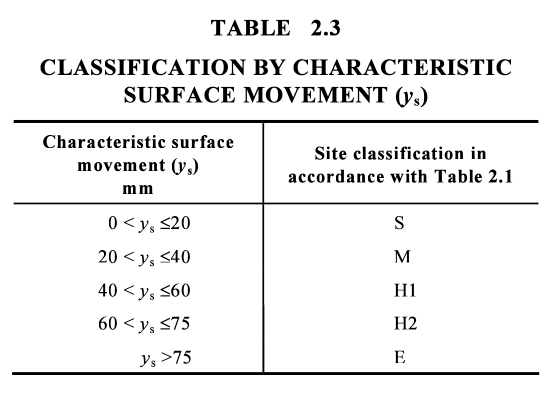
1.2 Characteristic Surface Movement
The characteristic surface movement (ys) refers to the expected vertical movement of the soil due to changes in moisture content. This movement can significantly impact the performance of a foundation. Sites are classified based on the expected surface movement, with classifications ranging from 0 to over 75 mm. The higher the movement, the more precautions must be taken to prevent structural damage.
Understanding these classifications allows builders and engineers to design foundations that can accommodate or resist the expected soil movements, ensuring the long-term stability of the home.
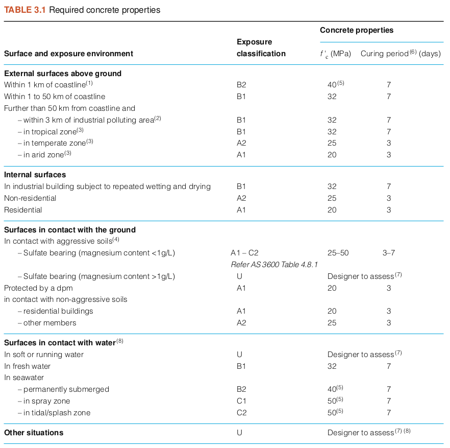
1.3 Exposure Classifications for Concrete
Another important consideration in foundation design is the exposure classification of the site, particularly in sulfate soils. Sulfate-rich soils can be highly corrosive to concrete, leading to deterioration if not properly addressed. The exposure classification system categorises sites based on the sulfate content in the soil and groundwater and the pH level.
For example:
- A1: Sites with low sulfate content and minimal exposure risk.
- B2: Sites with higher sulfate levels, requiring more robust concrete and additional protection measures.
The classification determines the minimum concrete strength required and the necessary measures to ensure the longevity and performance of the foundation.
For instance, higher sulfate levels necessitate the use of concrete with a higher characteristic strength (f’c) and more rigorous curing practices to protect against chemical attack.
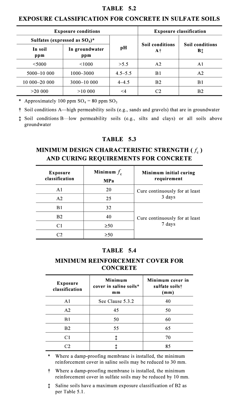
1.4 Minimum Design and Curing Requirements
Depending on the exposure classification, different concrete strengths and curing requirements are specified to ensure durability. For instance:
- A1 Classification: Requires concrete with a minimum strength of 20 MPa and continuous curing for at least three days.
- B2 Classification: Requires concrete with a minimum strength of 40 MPa and continuous curing for at least seven days.
Concrete Curing is also an important step in concrete construction, as it allows the concrete to achieve its intended strength and durability. Inadequate curing can lead to weaknesses in the foundation, reducing its ability to resist environmental stresses and chemical attacks.
Section 2: Pier and Slab Construction Elements
2.1 Pier Construction
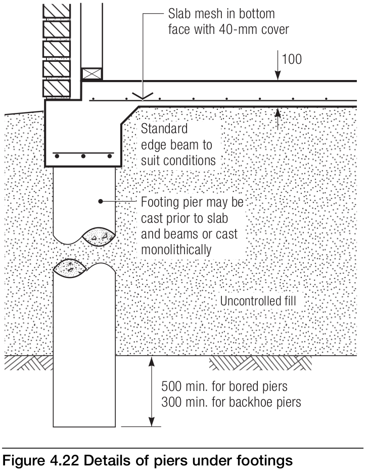
Piers are foundational elements that provide structural support by transferring the load of a building to deeper, more stable undisturbed/natural soil layers or rock.
Two common types of piers used in residential construction are screw piles (also known as screw piers or helical piles) and bored piers (also known as drilled shafts or caissons).
Each type offers distinct advantages depending on the specific requirements of the construction project.
2.1.1 Screw Piles
- Description: Screw piles are innovative foundation systems that consist of steel shafts with helical plates attached. These plates allow the piles to be screwed into the ground using hydraulic machinery, creating a stable and immediate load-bearing foundation. Screw piles are known for their ease of installation and versatility across various soil conditions, including soft soils, clay, sand, and even rocky terrains.
- Installation Process: The installation of screw piles is pretty quick and efficient, with minimal site disruption. An excavator (with attachment) screws the piles into the ground to the required depth, where they achieve immediate load-bearing capacity. This allows construction to proceed without delays, making screw piles a time-efficient solution.
- Bearing Pressure: Screw piles provide immediate load-bearing capacity as they are driven into the ground. The bearing pressure is achieved by torquing the screw piles into the soil until the desired resistance is met, typically ranging from 150 kPa to 300 kPa depending on the soil conditions. This process ensures that the piles are securely anchored in the ground, providing a stable foundation for the structure.
- Uplift Resistance: The helical design of screw piles offers superior uplift resistance compared to other foundation types. The helices increase the surface area of the pile, enhancing its grip within the soil and making it more resistant to uplift forces caused by wind, seismic activity, or other environmental factors. The ability to withstand such forces makes screw piles particularly suitable for areas prone to these conditions.
- Applications: Screw piles are versatile and can be used in a wide range of construction projects, including residential and commercial buildings, foundation underpinning, retaining walls, solar panel installations, and telecommunication towers. Their adaptability makes them a preferred choice in projects with varying soil conditions or where environmental impact needs to be minimised.
- One potential issue with screw piers arises when there is uplift, which can lead to the formation of a void between the pier and the surrounding soil. This typically occurs when expansive clay soils shrink due to a decrease in moisture content, causing the soil to pull away from the pier. The resulting void reduces lateral support, compromising the pier’s stability and load-bearing capacity. Without sufficient contact with the soil, the pier may lose its effectiveness in resisting both compression and uplift forces, ultimately affecting the overall structural integrity of the foundation.
- To mitigate this risk, the screw piers must be installed to a suitable depth where they remain anchored in stable soil layers, unaffected by surface moisture fluctuations. Additionally, proper site preparation and moisture control around the foundation can help minimise the likelihood of soil shrinkage and void formation.
2.1.2 Bored Piers
(they need more excitement in their life - don't we all!)

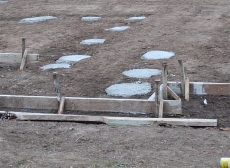
- Description: Bored piers are deep foundation elements created by drilling cylindrical holes into the ground and filling them with reinforced concrete. They are well-suited for projects that require high load-bearing capacity and deep foundations.
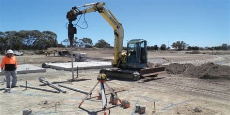
- Installation Process: The installation of bored piers involves using specialised drilling equipment to create deep holes in the ground, which are then filled with concrete and reinforcement. This process is more time-consuming and requires larger equipment compared to screw piles, making it more suitable for sites with ample space and access.
- Bearing Pressure: Bored piers provide high load-bearing capacity, making them ideal for supporting heavy structures. The depth and diameter of the pier are tailored to the specific load requirements and soil conditions, allowing for a flexible design that can accommodate various structural requirements.
- Uplift Resistance: Bored piers also offer excellent uplift resistance, particularly in cohesive soils like clay and silt. Their large diameter and deep embedment provide stability against lateral forces, such as those caused by earthquakes, making them a reliable choice in seismically active regions.
- Applications: Bored piers are commonly used in high-rise buildings, bridges, transmission towers, industrial plants, and other large-scale infrastructure projects. They are especially beneficial in projects that require deep foundations or have challenging soil conditions.
2.1.3 Screw Piles vs. Bored Piers: Which is better and when?
- Installation Process:
- Screw Piles: Quick and efficient installation with minimal site disruption. Suitable for sites with limited access and overhead clearance.
- Bored Piers: Requires specialised drilling equipment and is more time-consuming. Best suited for sites with ample space and access.
- Load Capacity:
- Screw Piles: Provides immediate load-bearing capacity and supports both axial and lateral loads.
- Bored Piers: High load-bearing capacity suitable for large-scale structures and heavy loads.
- Site Constraints:
- Screw Piles: Ideal for tight spaces and sites with challenging access conditions.
- Bored Piers: Requires larger equipment and more open space.
- Cost Considerations:
- Screw Piles: Generally more cost-effective due to faster installation and less site disruption.
- Bored Piers: Typically more expensive due to the need for specialised equipment and longer installation time.
- Time Efficiency:
- Screw Piles: Offers significant time savings, allowing construction to proceed quickly.
- Bored Piers: Installation takes longer, potentially impacting project timelines.
- Environmental Impact:
- Screw Piles: Minimal environmental disturbance with a smaller ecological footprint.
- Bored Piers: More extensive site disruption and a greater environmental impact.
- Flexibility and Adaptability:
- Screw Piles: Highly adaptable, with the ability to be removed and reused if needed.
- Bored Piers: Flexible design options but not easily removed once installed.
- Suitability for Different Soil Types:
- Screw Piles: Versatile across various soil conditions, including rocky terrains.
- Bored Piers: Best suited for cohesive soils and stable rock formations.
The choice between screw piles and bored piers depends on various factors, including site conditions, load requirements, time constraints, and budget.
Screw piles are often preferred for their speed, cost-effectiveness, and minimal spoil removal from site, while bored piers are chosen for their high load capacity.
2.2 Slab Construction
Concrete slabs form the horizontal foundation layer of a building, providing a stable base for the structure above. The construction of slabs involves several key components, each playing a role in ensuring the slab's strength and durability.
2.2.1 Components of Slab Construction
- Edge Beams: Edge beams are thicker sections of the slab that run along the perimeter of the foundation. They provide additional support where the walls of the building will be constructed. Edge beams help to distribute loads more evenly and prevent the slab from cracking or settling unevenly.
- Internal Beams: Internal beams, or ribs, are similar to edge beams but are located within the slab. These beams provide extra stiffness and strength to the slab, particularly in areas that will bear heavy loads, such as around load-bearing walls or under columns.
- Slab Thickening: Thickening refers to increasing the slab’s depth in certain areas to provide additional support. This is often done under heavy equipment, around columns, or at points where the slab will bear concentrated loads.
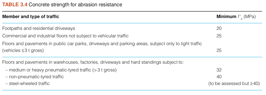
2.2.2 Concrete Types for Slabs
- Strength/Slump: The type of concrete used in slab construction must meet specific strength and slump requirements. Concrete strength is measured in megapascals (MPa), with common residential slabs requiring concrete in the range of 25 MPa to 32 MPa. The slump, which measures the consistency and workability of the concrete, is also critical. A slump of around 75 mm is typical for residential slabs, providing a good balance between workability and strength.
- Subgrade Preparation: Proper subgrade preparation is essential for a stable slab. This involves compacting the soil and adding a layer of crushed rock or gravel to create a solid base. The subgrade must be level and stable to prevent the slab from settling unevenly.
2.2.3 Damp-Proof Membranes (Vapour Barriers)
- Purpose and Placement: Damp-proof membranes are placed beneath the slab to prevent moisture from rising through the concrete and causing damage to the structure. The membrane also helps to protect against subsidence by providing a barrier between the slab and the potentially unstable ground.
- Integration with Edge Beams and External Walls: The damp-proof membrane should extend beyond the formwork and be wrapped up against the edge beams or slab edges. This helps to protect the foundation from moisture ingress and ensures the longevity of the structure. Read this very informative Cement, Concrete & Aggregates Data Sheet Explaining what Slab Edge Dampness is and how to prevent it:
 Anthony Painter
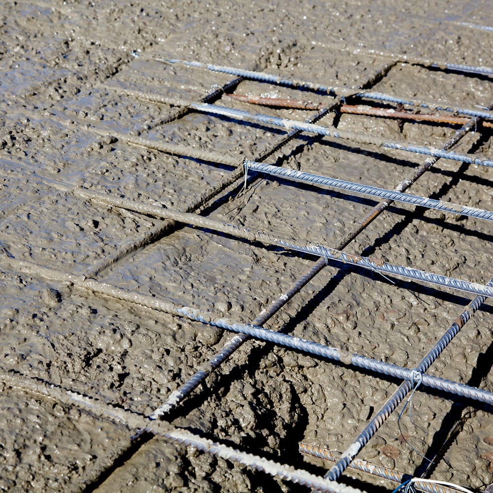
Section 3: Reinforcement Details in Concrete Slabs
Reinforcement is a required component in concrete slab construction, providing the strength and durability of the slab by helping it resist tension forces (concrete provides compressive strength). Proper reinforcement ensures that the slab can support the weight of the building and withstand external forces such as wind, temperature changes, and ground movement.
3.1 Types of Reinforcement
Reinforcement in concrete slabs typically involves the use of steel elements, which are embedded within the concrete to provide additional strength. The most common types of reinforcement used in residential construction include:
- Mesh: Steel mesh is one of the most widely used reinforcement materials in slab construction. It consists of a grid of steel bars welded together to form a network. The mesh is placed in the middle of the slab’s thickness to help control cracking and provide tensile strength. The most common types of mesh used are SL62, SL72, and SL82, where the numbers refer to the bar diameter and spacing.
- Bars: Steel bars, also known as rebar, are used to provide additional reinforcement in areas where extra strength is needed. These bars are typically used along with mesh in areas such as edges, around openings, and in beams within the slab. Rebar is available in various diameters, with N12 bars being common in residential slabs.
- Trench Mesh: Trench mesh is a type of steel reinforcement used specifically in footings and beams. It is designed to fit within narrow trenches and is often used in strip footings, raft slabs, and other applications where additional strength is required along a narrow, linear section of the foundation.
- Corner Bars: These bars are placed at corners or where the direction of reinforcement changes. They help to maintain the continuity of reinforcement and provide additional strength in areas that are prone to cracking.
- Ligatures: Ligatures, or stirrups, are closed loops of steel that are placed around the main reinforcement bars in beams or columns to hold them in place. They help to prevent the main bars from buckling and provide additional shear strength.
- Z Bars: Z bars are used in stepped or sloping slabs to maintain reinforcement continuity across the steps. They are bent into a Z shape to fit into the transition between different slab levels, ensuring that the reinforcement is properly anchored and that the slab remains structurally sound.
3.2 Slab Reinforcement Techniques
The placement and lapping of reinforcement are crucial to the performance of a concrete slab. Reinforcement must be installed according to the engineer's design and verified through a site inspection by the engineer before the slab is poured.
Additionally, we recommend conducting an extra pre-pour slab inspection alongside the engineer's inspection.
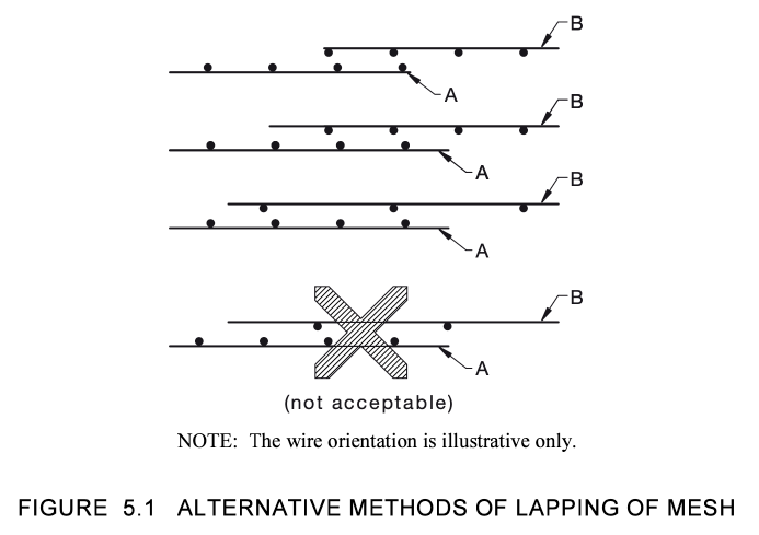
3.2.1 Lapping of Mesh
- Importance of Proper Lapping: Lapping is the process of overlapping steel mesh or bars to create a continuous reinforcement network. Proper lapping is required to prevent weak points in the slab where cracking could occur. The overlap should be sufficient to transfer the tensile forces from one piece of reinforcement to the next.
- Alternative Methods of Lapping Trench Mesh: There are various acceptable methods for lapping trench mesh, as shown in Figure 5.1 above. The correct method must be chosen based on the specific design requirements and the dimensions of the mesh and bars used. Incorrect lapping can lead to structural weaknesses (and non compliance with the engineers design).
3.2.2 Placement of Reinforcement
- Positioning within the Slab: Reinforcement must be positioned correctly within the slab to be effective. Typically, the reinforcement is placed in the middle third of the slab’s thickness. This positioning helps to control cracking caused by tension forces that develop when the slab is subjected to loads.
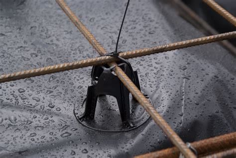
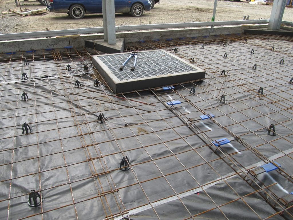
- Bar Chairs: One key component in ensuring that the reinforcement remains properly positioned during the concrete pour is the use of bar chairs. Bar chairs are small supports used to elevate the steel reinforcement bars and mesh to the correct height within the slab. This ensures that the reinforcement is embedded in the optimal location, typically the middle third of the slab’s thickness, which is required for maximising tensile strength and preventing concrete cracking.
- In driveway concrete pours, the use of bar chairs is particularly important due to the high loads that driveways must support. Vehicles exert significant pressure on the surface, and without adequate reinforcement placement, the slab may be prone to cracking and failure.
- Proper use of bar chairs in driveway slabs enhances durability, distributes loads more effectively, and contributes to the overall longevity of the concrete.
Bar chairs help maintain the proper clearance between the reinforcement and the formwork, ensuring consistent concrete cover and reducing the risk of corrosion due to exposure.
- Spacing and Cover: The spacing of reinforcement bars and mesh must be consistent and in accordance with the design specifications. Adequate cover (the distance between the reinforcement and the surface of the concrete) is also required to protect the steel from corrosion and to ensure the slab’s durability. Australian standards specify minimum cover requirements based on exposure classifications (e.g., 40 mm for A1 conditions, 65 mm for B2 conditions).
Anthony Painter
3.3 Curing Techniques and Times
Curing allows the concrete to develop its full strength and durability. Proper curing helps to prevent cracks and shrinkage and ensures that the concrete reaches the required design strength.
- Curing Methods: There are several methods used to cure concrete slabs, including:
- Wet Curing: Keeping the slab moist by applying water to the surface or covering it with wet hessian or plastic sheeting.
- Curing Compounds: Applying a liquid membrane-forming compound that slows the evaporation of moisture from the concrete surface.
- Curing Blankets: Using insulated blankets to retain heat and moisture, accelerating the curing process in cold weather conditions.
- Pond Curing: This method involves creating a dam around the slab edges and then flooding the slab with water, which is retained within the dam.
- Curing Times: The curing time required depends on the exposure classification and the concrete strength. For example: Adequate curing ensures that the concrete reaches its intended strength, making the slab more resistant to environmental stresses and chemical attacks.
- A1 Classification: Requires a minimum of three days of continuous curing.
- B2 Classification: Requires a minimum of seven days of continuous curing.
Anthony Painter
Section 4: Common Slab Terminology Explained
Understanding the terminology used in concrete slab construction is essential for anyone involved in residential construction, from home owners to builders.
In this section we will explain some of the key terms that are frequently encountered in the context of concrete foundations and slabs.
4.1 Understanding Key Terms
4.1.1 Cover to Reinforcement
- Definition: "Cover" refers to the distance between the outer surface of the concrete and the embedded reinforcement. This layer of concrete protects the steel from environmental factors, particularly moisture and corrosive agents, which can cause the steel to rust and weaken over time.
- Importance: Adequate cover is essential to ensure the durability of the concrete structure. The amount of cover required varies depending on the exposure conditions, with harsher environments requiring more cover. For instance, in sulfate-rich soils (B2 classification), a minimum cover of 65 mm is typically required to protect the reinforcement.
4.1.2 Slab Thickening
- Definition: Thickening refers to the intentional increase in the depth of the slab at specific locations. This is done to provide additional strength and support where higher loads are expected, such as under walls, heavy machinery, or columns.
- Purpose: The additional depth helps distribute the load over a larger area, reducing the risk of cracking or settlement. Thickened areas are typically reinforced with additional steel bars or mesh to further enhance their load-bearing capacity.
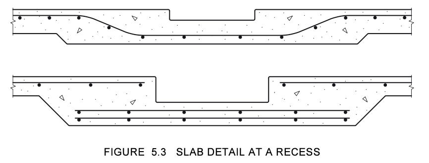
4.1.3 Slab Set Downs
- Definition: A slab set down is a step or recess in the slab where the level is lower than the surrounding concrete. This feature is commonly used in wet areas like bathrooms, laundries, and showers where a lower floor level is needed to accommodate waterproofing and drainage requirements.
- Construction Considerations: Proper reinforcement and careful attention to detail are necessary when creating set downs to ensure that the transition between levels does not become a weak point in the slab.
4.2 Foundation Protection Systems
4.2.1 Damp-Proof Membranes
- Purpose and Function: Damp-proof membranes provide a barrier that prevents moisture from rising through the concrete. This is particularly important in areas with high water tables or where the soil is prone to holding moisture.
- Placement: The damp-proof membrane is typically placed on top of the prepared subgrade before the concrete is poured. It should extend beyond the formwork and be wrapped up against the edge beams or the slab edge to ensure complete protection. This method helps prevent moisture from entering the foundation, reducing the risk of subsidence and protecting the structure from long-term damage.
4.2.2 Subsidence Protection
Explanation: Subsidence occurs when the ground beneath a structure shifts or settles, causing the foundation to move. This can lead to cracks in the slab and other structural issues.
See the image below:
4.3 Engineering Design Requirements
4.3.1 Reinforcement Cover Requirements
- Minimum Cover: As previously mentioned, the amount of cover required for reinforcement depends on the exposure conditions. For example, in environments with high sulfate content in the soil, a minimum cover of 65 mm may be required to protect the steel from corrosion. In less aggressive environments, such as those with low sulfate levels, the minimum cover may be reduced to 40 mm.
- Compliance with Standards: Ensuring that the correct amount of cover is provided is a key aspect of compliance with Australian building standards. Failure to provide adequate cover can result in premature deterioration of the concrete and reduced structural integrity.
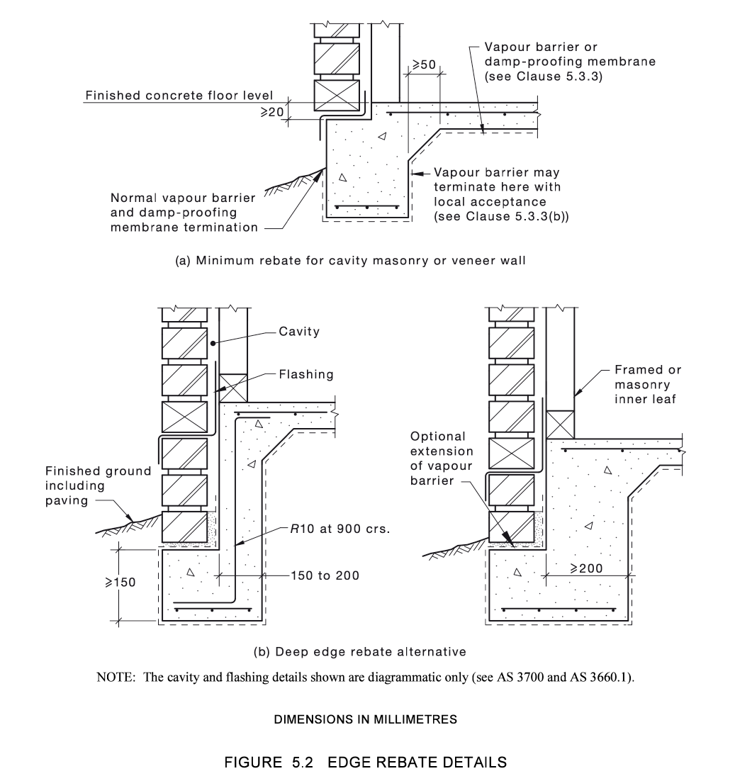
4.3.2 Edge Rebates and Slab Recesses
- Edge Rebates: Edge rebates are grooves or recesses formed in the edge of the slab to accommodate other construction elements such as walls or pavements. They provide a neat and secure connection point between the slab and the adjacent structure, helping to prevent water ingress and ensuring that the slab edge is protected.
- Slab Recesses: Recesses are formed within the slab to create lower areas, such as for wet rooms or service areas. Proper detailing and reinforcement are required to maintain the structural integrity of the slab in these areas.
4.4 Specific Joint Types
4.4.1 Control Joints
- Purpose: Control joints are intentionally placed weak spots in the slab that allow for controlled cracking. As concrete cures and shrinks, it is prone to cracking. Control joints help to manage where these cracks occur, minimising their impact on the overall structure.
- Placement: These joints are typically cut into the slab at regular intervals, depending on the size and design of the slab. Always follow the engineers design for the correct placement of control joints.
4.4.2 Isolation Joints
- Definition: Isolation joints are used to separate the slab from other structural elements such as walls or columns. This allows for independent movement between the slab and the adjacent structure, preventing cracks that could result from differential movement.
- Application: Isolation joints are essential in areas where different parts of the structure are expected to move independently, such as around columns or at the interface between a concrete slab and masonry walls.
4.4.3 Expansion Joints
- Purpose: Expansion joints accommodate the expansion and contraction of concrete due to temperature changes. These joints prevent the slab from cracking as it expands and contracts with changes in temperature.
- Construction: Expansion joints are typically filled with a compressible material that allows for movement while maintaining a seal against moisture and debris. They are commonly used in larger slabs or where the slab is exposed to significant temperature fluctuations.
4.4.4 Articulation Joints and "Expanda" Joints
- Articulation Joints: These joints are designed to accommodate movement in reactive soils, which can expand and contract significantly with moisture changes. Articulation joints allow different sections of the slab or structure to move independently without causing damage.
- "Expanda" Joints: Specifically used in plumbing and stormwater drainage systems, "Expanda" joints provide flexibility and movement in pipes that pass through or are embedded in concrete slabs. They prevent damage to the pipes and the slab caused by soil movement or temperature changes.
Check out our article on understanding the different types of concrete joints (below)

Section 5: Slab Preparation and Installation
Proper slab preparation and installation is required to ensure the long-term performance and durability of a concrete slab foundation. This section will cover the aspects of preparing the site, placing the concrete, and ensuring that the slab is installed correctly to meet Australian standards.
5.1 Subgrade and Soil Considerations
5.1.1 Importance of Subgrade Preparation
- Definition: The subgrade is the soil or base material that lies directly beneath the concrete slab. It serves as the foundation for the slab, providing support and helping to distribute the load of the structure evenly.
- Preparation Process: Proper subgrade preparation involves several key steps:
- Clearing and Grading: The site must be cleared of any vegetation, debris, and large rocks. The ground should then be graded to ensure a level and stable base.
- Compaction: The soil must be compacted to increase its density and stability. This reduces the likelihood of settlement or movement under the slab, which could lead to cracking or structural issues.
- Addition of Granular Material: In many cases, a layer of granular material such as sand, crushed rock (crusher dust) or gravel is added on top of the compacted soil. This layer, known as the base course, helps to improve drainage and further stabilise the subgrade.
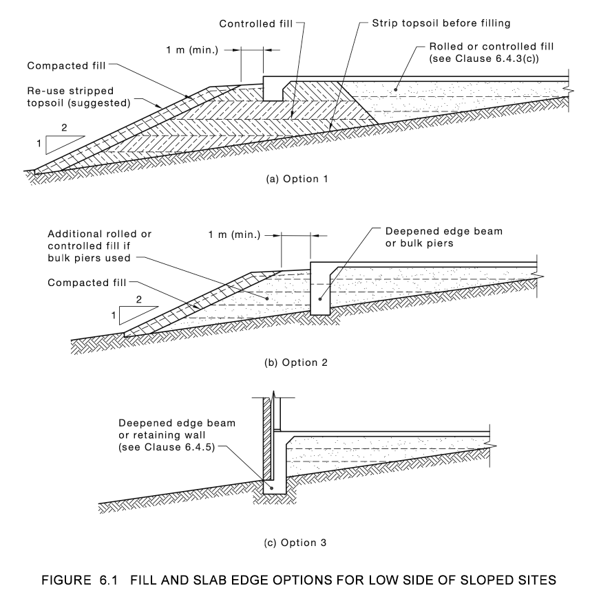
5.1.2 Dealing with Sloped Sites
- Challenges of Sloped Sites: Constructing a slab on a sloped site presents unique challenges, such as the need to accommodate varying soil levels and ensure that the slab remains level and stable.
- Techniques for Sloped Sites (See Figure 6.1 above)
- Stepped Footings: One common method is to use stepped footings, where the foundation is built in a series of horizontal steps that follow the slope of the land. This helps to maintain a consistent slab thickness and prevent uneven settling.
- Deepened Edge Beams: On sloped sites, edge beams may need to be deepened to provide additional support and prevent the slab from sliding or shifting. These beams act as retaining walls, holding the slab in place and distributing the load more effectively.
- Fill and Slab Edge Options: Depending on the slope and soil conditions, it may be necessary to use controlled fill to create a level platform for the slab. The fill must be compacted properly to prevent future settlement (reference to "Fill and Slab Edge Options for Sloped Sites" from the provided images).
5.2 Damp-Proof Membrane (Vapour Barrier) Placement
5.2.1 Purpose and Function
- Moisture Protection: The damp-proof membrane is again, a very important component in slab construction, acting as a barrier to prevent moisture from rising through the concrete. This is especially important in areas with high water tables or where the soil retains moisture.
- Subsidence Prevention: The membrane also helps to reduce the risk of subsidence by providing a stable layer that separates the concrete from the potentially unstable soil beneath.
5.2.2 Installation Best Practices
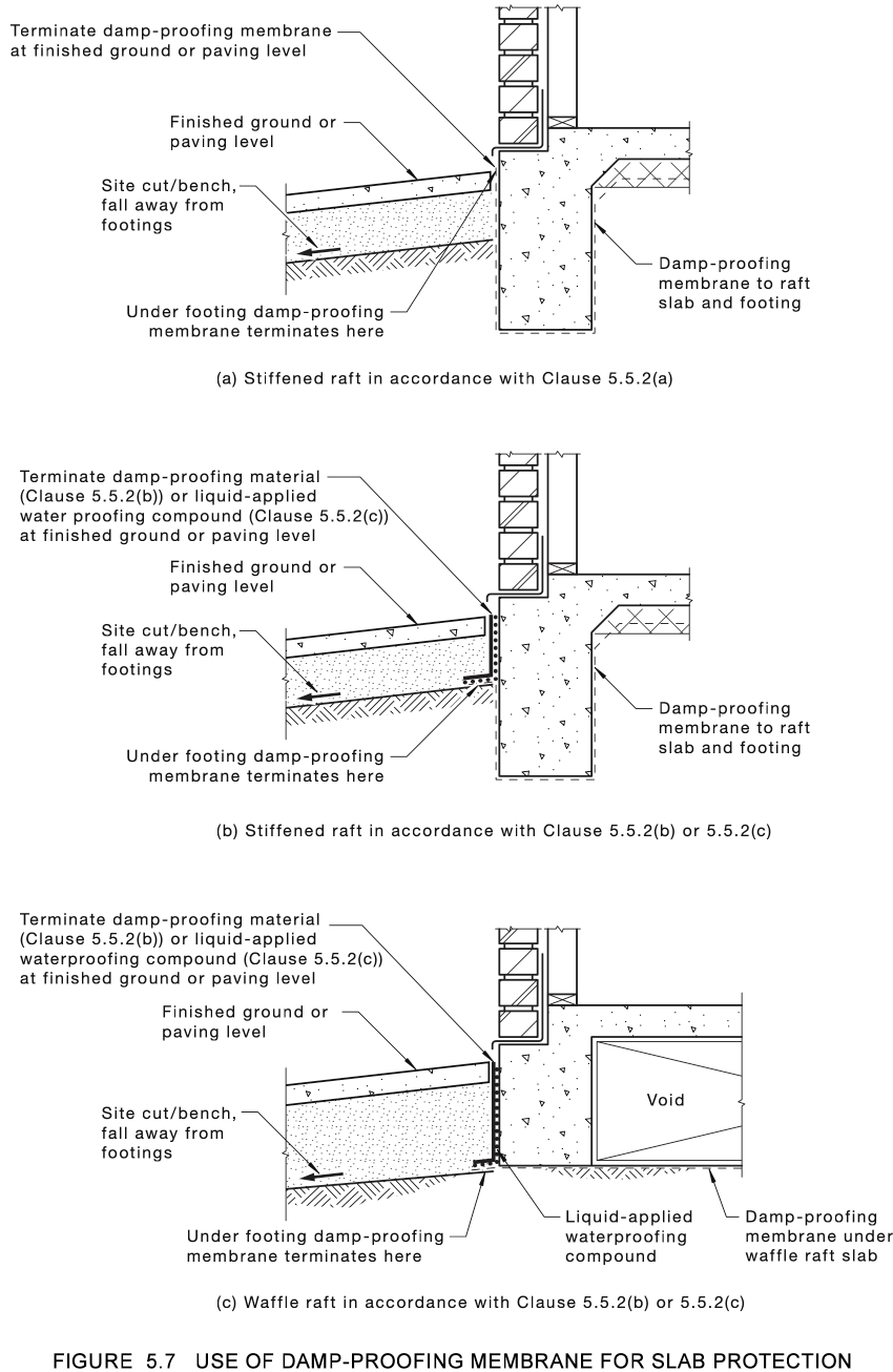
- Placement: The damp-proof membrane is typically placed directly on top of the prepared subgrade before the concrete is poured. It should cover the entire area of the slab, extending beyond the formwork to ensure full protection including the edge beam (see figure 5.7 above for details).
- Integration with Edge Beams and External Walls: The membrane should be wrapped up against the edge beams or slab edges to create a continuous barrier. This prevents moisture from entering the foundation and ensures that the slab is protected from all sides (see figure 5.7 above).
- Sealing Joints: Any joints or seams in the membrane should be properly sealed to prevent water from seeping through. This can be done using adhesive tape or a specialised sealing compound.
5.3 Concrete Pouring and Finishing
5.3.1 Concrete Pouring Process
- Preparation: Before pouring the concrete, it’s essential to ensure that all formwork is secure and that reinforcement is correctly placed and supported. The site should be inspected to confirm that the subgrade, damp-proof membrane, and reinforcement meet the design specifications.
- Pouring: Concrete should be poured in a continuous process to avoid creating weak spots. The concrete should be placed as close to its final position as possible to minimise the need for extensive movement or handling, which can lead to segregation of the aggregate and weaken the slab.
- Vibration: During the pour, the concrete should be vibrated to remove air pockets and ensure that it fully encapsulates the reinforcement. This is typically done using a mechanical vibrator, which is inserted into the concrete at regular intervals.
5.3.2 Finishing Techniques
- Initial Screeding: After the concrete is poured, it is screed to level the surface. Screeding involves dragging a straight edge across the top of the concrete to remove excess material and create a smooth, even surface.
- Floating: Once the concrete has set slightly, it is floated to further smooth the surface and embed any remaining aggregate just below the surface. This process also helps to bring the cement paste to the surface, creating a suitable base for the final finishing.
- Troweling: For a smooth, dense surface, the concrete is troweled after floating. Troweling can be done by hand or using a power trowel, depending on the size of the slab. This process creates a hard, durable surface that is resistant to wear and damage.
- Control Joint Cutting: After finishing, control joints are cut into the slab to allow for controlled cracking as the concrete cures. These joints are typically cut to a depth of one-quarter to one-third of the slab thickness and are spaced according to the design specifications. This practice is more commonly applied to driveways than to general concrete slabs, depending on the engineer's design requirements.
6: Challenges and Best Practices
The construction of concrete foundations and slabs comes with its own set of challenges, especially in residential projects where the quality of the foundation directly impacts the longevity and stability of the structure..
6.1 Common Challenges in Concrete Slab Construction
6.1.1 Subsidence and Soil Movement
- Definition: Subsidence refers to the gradual sinking or settling of the ground beneath the foundation, which can cause the slab to crack or shift. Soil movement, particularly in reactive soils, can also lead to foundation issues as the soil expands and contracts with moisture changes.
- Causes: Poor subgrade preparation, inadequate compaction, or unexpected soil conditions can lead to subsidence. In reactive soils, changes in moisture content can cause significant movement, which stresses the foundation.
- Impact on Slab: Subsidence and soil movement can cause cracking, uneven settling, and structural damage to the slab. This can lead to costly repairs and even compromise the safety of the building.
Read more about subsidence and how to mitigate it during construction in the post below:
Anthony Painter
6.1.2 Cracking and Shrinkage
- Definition: Cracking is a common issue in concrete slabs, often caused by shrinkage during the curing process, thermal expansion and contraction, or structural loads exceeding the slab’s capacity.
- Types of Cracks: Cracks can be categorised into several types, including shrinkage cracks, settlement cracks, and structural cracks. Each type has different causes and implications for the slab’s integrity.
- Causes: Inadequate curing, improper joint placement, overloading, or insufficient reinforcement can lead to cracks. Environmental factors, such as temperature changes or moisture fluctuations, can also contribute to cracking.
- Impact on Slab: While minor cracks may be cosmetic, significant cracking can compromise the slab’s structural integrity, leading to water ingress, reduced load-bearing capacity, and potential failure.
Again, this CCA Data Sheet Contains some fantastic information on Drying Shrinkage of Cement and Concrete. There are separate data sheets on plastic shrinkage cracking, drying cracking and settlement cracking, early age cracking, early cracking:
6.1.3 Water Ingress
- Definition: Water ingress occurs when water penetrates the concrete slab, either through cracks, joints, or from below the slab. This can lead to a range of issues, including corrosion of reinforcement, weakening of the concrete, and increased risk of subsidence.
- Causes: Poor joint sealing, inadequate damp-proof membranes, and improper slab detailing can allow water to enter the slab. In areas with high water tables or poor drainage, water ingress is a significant concern.
- Impact on Slab: Water ingress can cause the steel reinforcement to corrode, weakening the slab and leading to structural issues. It can also cause the slab to heave or settle unevenly, resulting in cracks and other damage.
The Consequences of Cutting Corners: Why Standards Are Often Ignored
While concrete construction in residential projects is governed by Australian standards, such as AS 3600 and AS 2870, it is unfortunately common for trade contractors to neglect these guidelines. Instead of adhering to the standards, many contractors simply rely on practices they have "always done" or opt for methods that allow them to "get away with it" to save time and increase profits. This often results in substandard work, which can compromise the integrity of the concrete and lead to long-term issues.
Knowing this, home owners and project managers are in a better position to quality manage their concrete pour by being aware of these requirements, alongside involving structural engineers for necessary inspections. The information needed to ensure quality is readily available, and contractors can easily create simple quality control checklists and quality management processes.
Inspection Test Plans (ITPs) are also freely available online for purchase, typically around $90, and can serve as an excellent starting point for contractors or companies genuinely interested in improving their quality management.
This proactive approach ensures that work is done properly rather than simply "taking orders." A combination of incentives and enforcement ("carrot and stick" approach) is necessary to improve quality control and management.
Currently, there is little motivation beyond the contractor's personal morals and ethics to adhere to proper standards.
A Quick Note on Driveways & Paths
If was to pick one document from this post that I highly recommend, it's the CCA document on Residential Driveways and Concrete Paths. It will provide valuable insights into how concretors should be doing their work, compared to the typical practices they often follow.
Home Owner Maintenance
Proper maintenance of your home's foundation is required to minimise the risks of soil movement and protecting the structural integrity of your home. The following best practices are recommended to help home-owners maintain their foundation effectively:
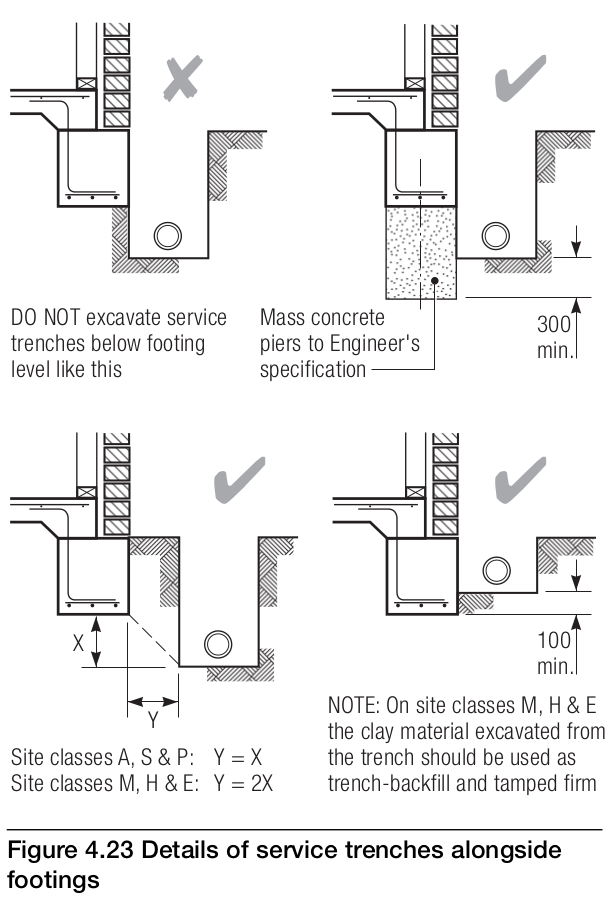
- Manage Soil Moisture Levels: One of the most common causes of foundation movement is the expansion and contraction of clay soils due to fluctuating moisture levels. To prevent this, maintain consistent soil moisture around the foundation. Avoid excessive watering, and ensure garden beds near the house are kept well-drained.
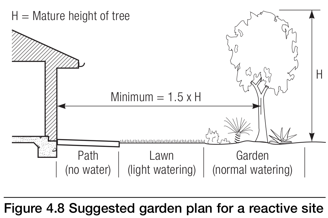
- Control Tree and Shrub Growth: Trees and shrubs planted too close to the foundation can cause significant soil shrinkage as their roots extract moisture from the soil. It is advisable to plant trees and shrubs at a safe distance from the home. If you suspect root issues, consider installing root barriers or relocating the trees to prevent upward pressure or soil drying under footings.
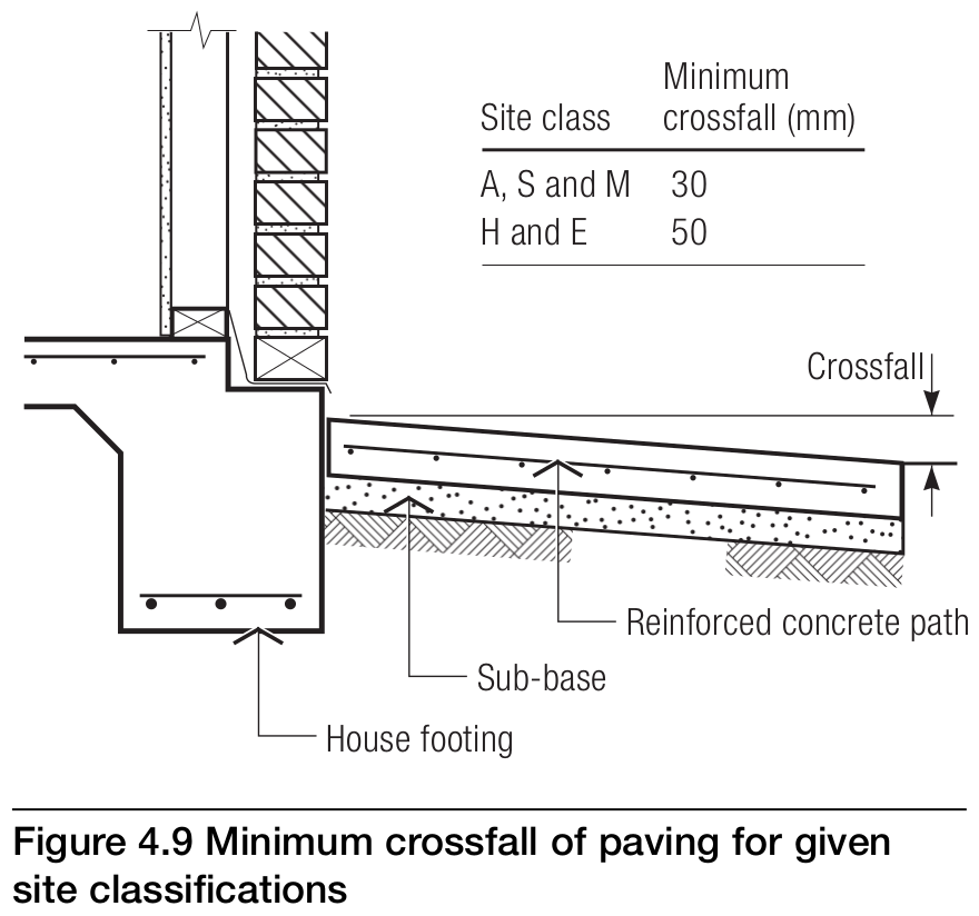
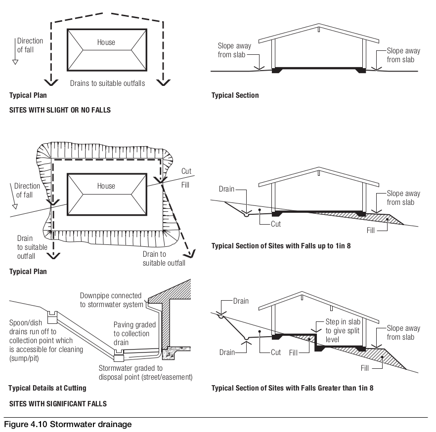
- Proper Drainage and Surface Water Management: Ensure that water drains away from the foundation. Install graded paving around the perimeter of the building to direct rainwater away, and avoid letting water pool near the foundation. Fix any leaking pipes, guttering, downpipes or air-conditioning condensate pipes discharging to the soil (and not into the drainage system) that could lead to soil saturation, as this may weaken the soil and cause subsidence.
- Address Erosion: Sandy soils are particularly susceptible to erosion, which can lead to the undermining of footings. Keep the soil around your home intact by preventing surface runoff and considering retaining solutions like paving or ground covers.
- Monitor for Cracks and Structural Changes: Regularly inspect your home for signs of foundation movement, such as cracks in walls, uneven floors, or doors and windows that no longer close properly. Addressing these issues early can prevent more extensive damage.
- Professional Inspections: Periodically engage a structural engineer or foundation specialist to inspect your home, especially if you notice significant cracking or movement. They can provide qualified advice and remediation strategies, ensuring your foundation remains stable and safe.
Conclusion
Concrete foundations and slabs are the backbone of any residential structure, providing essential support and ensuring the building’s stability and longevity. From understanding soil conditions to selecting the appropriate type of pier, reinforcing the slab, and managing challenges like subsidence and water ingress, every step of the construction process plays a role in the success of the project.
However, the reality of construction is that quality often suffers due to shortcuts taken by contractors seeking to save time or increase profit. While the Australian Standards (AS 3600 and AS 2870) and comprehensive data sheets from the CCA (Concrete Cement Aggregate) Association provide clear guidelines for high-quality concrete work, many contractors choose to ignore these in favour of "what they've always done."
Home owners and construction managers, building supervisors are best positioned to ensure quality by being informed, utilising structural engineers for inspections, and leveraging simple quality management processes, such as Inspection Test Plans (ITPs).
It is clear that, in the absence of regulatory enforcement, a "carrot and stick" approach is required to drive improvements in quality control and management. With the right knowledge and tools, home owners can actively contribute to the success of their concrete foundation and slab, ensuring a safe, stable, and durable home.
FAQs
- What is the role of steel reinforcement in concrete slabs?
- Steel reinforcement, such as mesh and rebar, provides tensile strength to the concrete, helping to resist cracking and structural failure due to loads and environmental factors.
- How do I know if my soil type is suitable for a concrete slab foundation?
- Soil testing and classification (e.g., Class A, S, M, H, E) are essential to determine the soil's reactivity and load-bearing capacity. A professional engineer can recommend the appropriate foundation type based on these results.
- What is the importance of curing, and how long should it last?
- Curing allows the concrete to reach its full strength and durability by retaining moisture. The curing period typically lasts between 3 to 7 days, depending on the exposure classification and environmental conditions.
- Can a concrete slab be used on a sloped site?
- Yes, with proper techniques such as stepped footings, deepened edge beams, and controlled fill, concrete slabs can be successfully constructed on sloped sites.
- What are the signs of a poorly constructed concrete slab?
- Signs include significant cracking, uneven settling, water ingress, and exposed or corroding reinforcement. These issues often result from poor subgrade preparation, inadequate curing, or improper joint placement.
- What is a damp-proof membrane, and why is it necessary?
- A damp-proof membrane is a barrier placed beneath the slab to prevent moisture from rising through the concrete, protecting the slab from subsidence and water damage.
- How do expansion joints prevent cracking in concrete slabs?
- Expansion joints allow the slab to expand and contract with temperature changes, preventing uncontrolled cracking by providing space for the concrete to move.
- What are the benefits of using bored piers over screw piers?
- Bored piers offer better uplift resistance due to the surface resistance and cohesiveness of surrounding soil, which provides greater surface area and stability. Bored piers will not fail in the same way that screw piers can due to seasons soil movement.
- What is slab set down, and when is it used?
- A slab set down is a recessed area within the slab, typically used in wet rooms like bathrooms to accommodate drainage and waterproofing requirements.
- How do I maintain my concrete slab after construction?
- Regularly inspect the slab for cracks, reseal joints as needed, ensure proper drainage around the slab, and address any signs of water ingress or settlement promptly.
Further Reading
Anthony Painter Anthony Painter
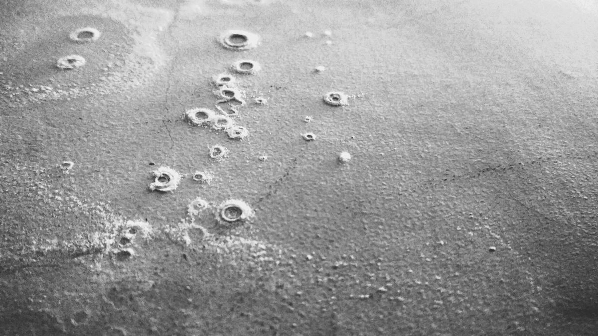 Anthony Painter
 Anthony PainterAnthony Painter


Member discussion